A NEW ‘WRINKLE’ IN FOLDING BASEBOARDS!
A NEW ‘WRINKLE’ IN FOLDING BASEBOARDS!
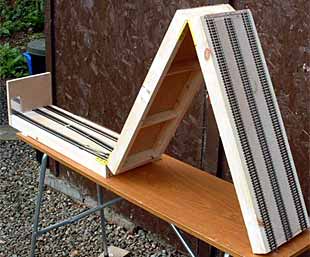
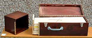
Jack Trollope, who lives in the Highlands of Scotland, was interested in my design for the Folding WayTerminal (left above), and actually built it! The photo (above right) shows his result. The baseboard is a light wood framework covered with composition board. Hinges (below right) are from a plastic, folding carpenter’s rule (the only ones he could find that were narrow enough to fit between the track and the edge of the baseboard)!
Jack comments, “The main board including end-scene is 24.75″ long, the others are 24”. All are 1.75″ deep and a fraction under 8″ (about 7 7/8″) wide, to allow them to slide into the box (photo below).
“The intention is to have two drop-on highway overpass bridges that slot over the hinges. The back scenes will drop into slots at the rear of the bridges to hold everything in place. I think that, given a bit of dimension juggling, I can get both the bridges and the backscenes into the box too.”
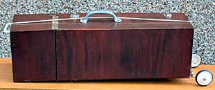
The box is shown below (both open and closed with carrier wheels attached). This is the same box that contained Jack’s original, classic Box Street Yard!
SECTOR PLATE TIPS 1: ARMSTRONG’S ARC
Speaking of Box Street Yard, Todd Armstrong, who lives in Ontario, Canada, is building a larger version of that design and has produced a very well-engineered sector plate to serve the layout.
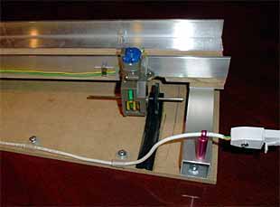
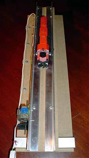
He reports, “It’s made of hardboard and aluminium angles set 16.5mm apart. At one end, there is a ball bearing swivel plate and at the other end a motor and reduction gearbox. Power is switched between the drive motor and rail via a latching relay.”
Todd used a widely-available Tamiya 5402:1 reduction gearbox and motor to drive the sector plate via a gearplate that was curved with a heatgun to the proper radius.
SECTOR PLATE TIPS 2: GILBERT’S GYRATION
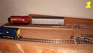
Chris Gilbert, who lives in the West Midlands of England, designed and mocked up an ingenious sector plate design. On his projected layout, sidings under the brick works are accessed by sector plate which also permits the train to be turned 180 degrees! The secret is a diagonal “slot for sliding” that allows the plate to be reversed while a train occupies it … so the locomotive can work from the correct end of the train in either direction!
Follow the photos to see how Chris’s mockup works:
1. Train enters sector plate from hidden siding.
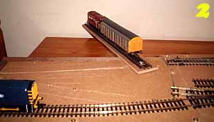
2. Sector plate swings out on pivot.
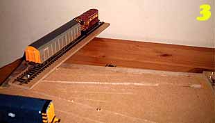
3. Pivot point slides in slot to other end!
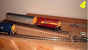
4. Plate continues swing to line up with layout track, loco first.
TRAVERSER (TRANSFER TABLE) TACTICS 1: HOLMES’S HIGHLIGHT
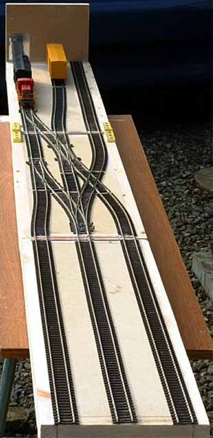
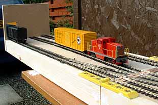
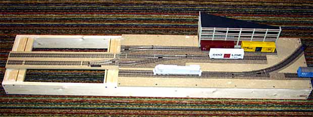 From northern Minnesota, Ian Holmes sends this work-in-progress photo of his layout, Watching the Trains. A feature of this design is Ian’s use of a divided crossover, half visible on the layout and half hidden on the traverser, to add flexibility to his shunting capabilities. He reports that it’s working “just fine”. Notice that the traverser (transfer table) slides on two metal bars, which also carry current to the rails via brass channels embedded in slots under the table.
The layout models a single industry reached from a busy main line. Ian is using the City Classics modular industrial building kit, Smallman Street Warehouse, to tailor the industry to his space and needs. With luck we’ll have more photos as construction progresses on this well-designed little line.
TRAVERSER (TRANSFER TABLE) TACTICS 2: ARENDT’S ARTIFACT
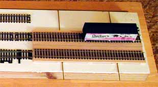 Awhile back, I designed a simple traverser that anyone can make for very little cost. It’s called the Poor Man’s Traverser (PMT), and it’s described in some detail in my book, Creating Micro Layouts (page 20). Here’s the basic concept of the table, which should be enough to get you started on building one:
“The PMT is basically a platform of stripwood with two crosswise slots to hold 1/8″ (3mm) brass channels that slide on Code 100 rails glued down with contact cement. The trick is to keep things absolutely square. Power is fed via the cross-rails and channels to the track rails.”
From my limited exposure to the site it is promising. Look forward to reading more articles.