Wiki Articles: Construction and Operation

Construction/Operation
(Click or Browse)
Animations for Small Layouts
Cheap and Easy Baseboards
Operating Hidden Staging
Turntable Wiring Alternative
Tymesaver on a Hollow-Core Door
Animations for Small Layouts
On Chris MacKenzie’s 16mm (SM32) exhibition layout, Timpdon Lake, the animation most popular with children concerns a group of workmen around a hole in a road. A sign on the fascia of the layout invites spectators to push a button to see what the workmen are doing. This results in a fountain of water, artfully directed to soak the victim. The reservoir and pump are from an auto screenwash. The reservoir requires frequent refills.
See the video clip. (Watch the timer. At 03:56 / 06:23 you will see this animation.)
– John Angell
P.S. Chris !MacKenzie has just posted a clip of his latest animation!. (He never ceases to amaze me.)
In your Animations Bibliography in Scrapbook #64, you missed a fairly recent and major US publication: A Beginner’s Guide to Creative Effects for your Model Railroad, by Paul Newitt, 2005. Published by J-T Publishing, ISBN 0-9760864-0-9.
It’s 200 pages long, profusely illustrated, and has a whole lot of material. Highly recommended.
– Charles Hansen
Thank you for the very kind description of our small layout, Atmosphére tarnaise, in Scrapbook #64 of your excellent site.
In our club, we enjoy imagining such small animated scenes. On the club layout (freely open to visitors every Saturday afternoon), we installed a few others. Some of them can be seen on our website. Select “visite” then in the “SOMMAIRE” (at left), select “Videos”.
– Michel Viers, Rail Miniature Castrais
This is one of the most amazing animations I have seen. Go most of the way towards the bottom where you will find a load of photos and links by Christopher (Trainclown). The videos are incredible — he must have Swiss Cuckoo-Clock makers in his ancestry.
And the whole thing is built upon/around a Peanut Butter Lid!
– Jack Trollope
I enjoyed your monthly scrapbook about animation and want to send you a link. Just look at the video.
– Werner Seyfried
Look here.
– Jack Trollope
I was reading through Motion Notions, Scrapbook #64, and it got me thinking about the hot air balloon and lifting it in a direction other than vertical with a flat ceiling.
Well I came up with a few ideas depending on valances and backdrops:
1. Starting with the winch described on page 64, mount it somewhere off center of the balloon.
- Route the line through an eye-hook at the end of a rod or stick, lightly sprung.
- Tie a knot in the line between the eye-hook and balloon.
- As the motor starts, the balloon lifts vertically (maybe with a little shimmy from the springing). When the knot hits the eye-hook some lateral movement will be added.
- Various rod fastening positions and hinge types could create different paths of travel.
- If someone wants to get really fancy, some type of block and tackle arrangement with the winch pulling to the side should create two different speeds in two axes.)
2. Got a few other ideas, but this isn’t the balloon animation scrapbook, now is it? Still playing with the takeoff/landing on opposite sides of a backdrop…
Over center divider/backdrop, a stall motor is attached to spool of line (affixed for horizontal spin) threaded through a horizontal rod. Rod suspended from ceiling from larger bracket at far (balloon) end and smaller bracket (motor end) to allow for traversing. A knot tied between the rod and balloon.
Turn on the motor and th balloon lifts until the knot hits the rod. This pulls the rod closer to the spool, causing the rod to swing in that direction, when the rod hits the far stop, the motor stalls, auto reverse lowers the balloon to the ground vertically. After the balloon touches down, and the line is spent, it will automatically start to rewind, starting the sequence in reverse. Get it?
But this isn’t the balloon animation scrapbook….
– Terry from Maine (USA)
I remembered you were looking for animations on layouts – here are a couple of clever ones:
– Jack Trollope
Working tippers.
These thoughts are based on the use of Gnomy tipping wagons, with the toy chassis replaced by a Sidelines chassis for modellers using 16.5mm gauge. The tippers are modified by having a length of small-section brass bar super-glued at an angle part way down one end, and projecting out approximately 10mm, like a finger.
When the train arrives at the plant the fingers engage with a sloping metal bar or thin tube situated alongside the track; as the wagon is moved forwards the finger is forced to rise, eventually tipping the load off on the opposite side of the line. The sloping wire will start outside the wagon’s loading gauge, and gradually move across towards the track’s centre-line as it rises to clear the wagon body — trial and error will be needed here, depending on the wagon being used.
Just beyond the tipping point the metal bar should bend back towards the track edge, allowing the finger to run off the end and the tipper to right itself; in this way a train of several tippers may be run past the tipple. Running in the reverse direction the fingers may just catch the underside of the angled bar, but the wagon skips should only jiggle as they pass. Care may need to be taken positioning the angled bar if the locomotive is to pass through the tipple area. It may be necessary to use only low-bodied prototypes, like battery-driven mining locomotives.
The tipping mechanism is delicate and would benefit from being soldered to a beam bridging the track at the upper end, but this will need to be high enough to allow the wagons to right themselves without fouling the bridge. It would be an advantage to build an open sided shelter over the tipple to help mask the workings and for protection from accidental knocks.
If you plan to use N gauge track, suitable tipping sets are available commercially – the tippers being rather oversize in N, but just right for 009 or O9. Apart from altering the tipping mechanism to accommodate the larger scale there is no more work to do.
– Giles Barnabe
Cheap and Easy Baseboards
Perhaps these are the cheapest and easiest layout baseboards you can find.
In a word (two words actually): folding tables. The pre-built kind, which you can get through Amazon and lots of other places. Adhere your pink/blue foam or other subroadbed/scenery base to the tabletop, and you’ve got an inexpensive and (probably, choose wisely) lightweight layout that folds up when not in use.
I’ve noticed there are some common sizes which seem particularly well suited for N scale (or for small layouts in larger scales), including 30x72in, 2x4ft, and 34in square. There are even some round folding tables, but they’re pricier.
– By Gabriel G. in Model Railroaders Anonymous
Another choice that is solid and flat is the hollow core door. I went to my local home improvement store and bought a slightly damaged door for next to nothing. It is strong (torsion box), flat and light. I attached a simple handle to one edge and it carries easily, although it’s 78 in long. Since I model in On30, I have expanded a micro layout into this larger space. It rests on two saw horses when in use by my grandchildren.
– by Bob V.
Hollow core doors are a great boon for the un-handy person. They come in widths from 12in (half a bi-fold) to 36in. The length is standard at 80in (6ft-8in). However, this dimension is easily made shorter using only hand tools.
If you mount legs there must be additional support added across the door. The door’s strength is only in 1-1/2 inches of the sides. I used 1×4 stock and screwed into the outer edge. Use the full width reinforcement, even if you use the screw-in legs.
I shortened one of these for a neighbor. I attached fixed casters to one end. His 8-year old can stand the door on end and roll it through the closet door for storage. Sadly the door has a slot-car track on it.
Shortening a door is easy. Cut across the door at the desired length. From the discarded piece remove the wood frame. Do this by prying the skin from the frame. Cut the bottom piece from the frame. Then remove enough of the cardboard filler from the remaining door so the bottom piece fits flush with the end of the door. I found a screw makes an ideal handle for removing this piece during test fitting.
Apply glue on all sides inside the cavity you created, then insert the bottom piece. Using small nails, not brads, tack the bottom piece in place or apply pressure by clamping or weighting. I also used nails from the sides of the door into the bottom frame.
I did all this on-site using a handsaw, hammer, and a kitchen veggie knife. The knife was abused  I used it to pry the skin off the frame. It also split the bottom from the rest of the frame. Then it was used to plane away remaining wood splinters from all pieces. It was a knife from his garage. All this was done in less time than it would have if I went home and gathered my power saw and sophisticated hand tools.
– Glenn Hazel
Or try Ikea Amon table tops, which come in a variety of sizes, and seem to be a bit like hollow-core doors, cheap too. They sell cheap trestles as well.
– Kevin P.
To add to Kevin’s comment, at IKEA you can find table legs with simple attachment points that can be fitted to a wide range of table tops. Also, they offer out of the box cheap tables — such as IKEA North America’s line called VIKA which includes several easy to use table and leg combinations that would be ideal for small layouts.
One really good option is the VIKA GREVSTA VIKA OLEBY. It is a bit more expensive but nice in appearance all around. It’s a bit pricey, however, at 109.99 USD.
The most affordable option is the VIKA AMON VIKA CURRY, which retails at just 34.99 USD. It measures 39-3/8in (100 cm) x 23-5/8in (60 cm) and is 27-1/2in (70 cm) high.
Finally, for those who want a large pizza, it would be easy to adapt the VIKA MANNE VIKA CURRY to the task, as it measures 43¼in (110 cm) diameter, is a standard table height, and as well is quite affordable for a round table at just 59.99 USD.
All of these links and prices are from February 2008.
– Thomas Van Hare – Oh To Fly!
In the US, Lowes (maybe Home Depot too) carries a plastic topped version of the good ole banquet table. The steel legs fold in the familiar style. They are about 1/3 of the weight of the older tables. Mine is about 24 x 48. There was a larger 30×60 and a square craft table too. This model has a flat work surface plus recesses for holding tools, etc. This small table would be idea for working in front of the TV with the family.
Look at the Blow Mold tables. The craft table is not listed, but was available in the stores.
– Glenn Hazel
I had an around-the-room layout, 12x16ft, several years ago when one of my neighbors replaced the interior doors in his house. I still have some for the layout in my new house. A couple of the other doors are workbenches.
I use two techniques for legs. #1 was a pair of cheap saw horses to support a single door at Christmas. The second, used for the around-the-room, was based on l-girders to support the doors and 2×4 legs with T-bolts on the bottom to adjust the height. Worked great for me and wasn’t anywhere near the prices that I’ve seen above.
Good Luck with your endeavor.
– John Mensch
I had a brain wave earlier this week whilst wondering around a 24hr supermarket at 1.30am. A great idea for an instant basedoard is the relatively inexpensive cork pin board/noticeboards. Over here in the UK they are less than £3 and the one I picked up had a rather sturdy softwood frame which offers good support. The back is supported by cardboard which for a little more stability could be thickened easily enough. Mine measures 60x40cm. You could even hang it up when not in use!
Greetings to all! – DT
Operating Hidden Staging
Traversers, sector plates, train turntables, and other tools of the Micro Layout Designer are ingenious ways of packing the fucntional equivalent of entire turnout-style yard ladders into very small spaces. However, actually operating them takes a bit or preplanning, so you can gain all the layout design and space benefits without confusing your operators or compromising the “look” of the layout.
In practical terms, there are three ways to operate such devices.
1 – Hands on
This literally involves the operator manually manipulating the traverser or sector plate.
PROS
– Dead simple
– ease of installation and implementation
– readily contructed using “off the shelf” materials
– ease of track alignment (by eye)
CONS
– in order to allow “manual” control, visual subterfuge such as the placing of traversers and sector plates behind larger warehouses and other “staging props/backdrops/scene breaks” is compromised
– retaining visual breaks may dictate operation from the rear of the layout, which does not encourage “crowd interaction” between operators and punters at shows (i.e., where operation from the front may be desirable)
– operation from the front is also effectively what shelf layouts encourage, again presenting an operational access challenge
– hard for new operators, (and even old hands!), to reconcile the functional sectorplate/traverser track system with any realistic turnout-based track arrangement.
2 – Manual Control via remote mechanism
This can be a variation on the traditional “wire in tube” method, with a suitable manual knob type control available at either the front or rear of the layout, (or both! ;-).
PROS
– Not that much more complex than a basic manual system
– readily implemented using off the shelf materials
– ease of track alignment (by eye)
CONS
– hard for new operators, (and even old hands!), to reconcile the functional “sectorplate/traverser” track system with any realistic turnout-based track arrangement
3 – Remote control via electro-mechanical system
Using a worm-drive or slow-motion-motor based switching mechanism, driven by a basic “stall-motor driver” circuit, to operate the traverser/sector plate
PROS
– can be linked to a more “logical” track-schematic based control panel, thus hiding the base track-arrangement subterfuge which the traverser/sectorplate represents
– system can be fully hidden behind “warehouse viewblocks”, thus not compromising the believability of the layout scene to viewers
CONS
– more complex assembly (requires both mechanical and electrical skills)
– reliability of the system MUST be high to ensure that home operations are not frustrating and that show operations are not compromised
Now, I’m not sayings that all layouts that have a sector plate or traverser must choose any one of the above solutions, but I would suggest that there are more than simply trackplanning considerations that must be taken into account.
- If a layout will be primarily operated by its owner in a home layout environment, then the aesthetic and user-interface compromises required to implement a manual-operation solution may be acceptable.
- For layouts intended to go to shows, a manual-via-remote system has a lot going for it. Mechanically simple and reliable, yet still allowing either front or rear operation of the layout. Easy to construct and operate, and yet still allowing the traverser/sectorplate to be fully hidden from the viewing public, thus not compromising the “presentation” of the layout display.
- However, regardless of whether the layout is intended for show work or home-layout duty, if the layout is intended to be operated by more than one operator, then the user interface needs to make sense at a glance. This is especially true for guest operators or viewers who may take up the invitation to drive a train on a home layout.
Compared to a regular yard-ladder track arrangement that even a non-train viewer can understand, a traverser or sectorplate can present a confusing piece of trackage. How does it work? What track goes where? How to I get from Point A to Point B if the traverser is involved?
The “electrical control system” option allows the builder to mate that functional traverser/sectorplate arrangement on the model layout with a more understandable-at-a-glance track-diagram representation on a simple control panel. “Ease of Use” of the layout controls makes for happy operators and a smoother operating experience, especially under public show conditions.
Hope This Helps,
Happy Modelling, Aim to Improve, Prof Klyzlr
Turntable Wiring Alternative
A thought on the recent easy turntable FAQ. I remember from years ago that someone published another way of wiring up a turntable.
The idea is to purchase a ¼in standard phone (microphone, not RCA phono) plug and jack set (monaural rather than stereo, although the stereo set will work). Mount the jack into the base of the turntable pit, using the nut and washer to secure the jack. It needs to be exactly centered.
The plug portion, less the cable shroud, is secured and centered beneath the turntable deck. The deck can be “plugged” into the pit and jack, and removed easily. The deck will rotate easily around the jack and stay centered. The jack will have two electrical leads for power and the turntable rails can be wired to the two connections on the plug. You will still need a DPDT (Double Pole, Double Throw) switch to reverse power to the turntable.
As I remember the deal a ¼in phone set was used. This was prior to the development of micro 1/8in plug and jack sets. It was also prior to such things as N gauge or Z gauge. I guess for the smaller scales a 1/8in set might be needed but the wiring and installation might be a little more difficult.
– Frank Edgcombe, USA
Actually it’s a good idea to use the stereo version of the plug and socket (three poles) and to wire the power to the tip and sleeve (missing out the middle contact). This is because there is a chance that you could short out the incoming power if you plug or unplug the jack (read turntable in this case) as the tip of it will momentarily touch both the contacts on a mono socket. I hope that makes sense!
– Andy Bantock, UK
The stereo type would be excellent. If you have a fancy turntable, the third conductor could be used for constant voltage for the overhead lights or lighting in the operator’s shack :).
The phone plug can also be used for connecting sector plates and cassettes.
– Glenn Hazel
Tymesaver on a Hollow-Core Door
While it’s not quite a micro layout, I built this Tymesaver to test hollow-core doors and rigid foam as a structure for a shelf layout. I hope to integrate it into a larger layout. The combination worked quite nicely and is very rigid and light.
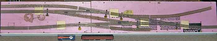
The door is half of a used set of folding doors; it is 12 inches wide and a standard 80 inches long. The whole thing with foam is about 15 lbs and unbendable. Hollow-core doors are honeycombed with corrugated cardboard, which is an excellent design for rigidity. I hang it from the wall with light adjustable brackets.The 80 inch length permits a run-around for a 60 ft passenger car or two 40 ft box cars (pictured at the bottom for scale).
The track is Atlas code 83 with Custom-Line turnouts and Caboose Hobbies ground throws. The squares of manila cardboard conceal Kadee under-track permanent magnets for uncoupling. The magnets slide out from under the track to prevent accidental uncoupling. They are connected under the structure to rigid wires you push or pull from the front edge. The bottom of this picture is the front. The wires are metal coathangers cut and bent to fit.
And I still have the other half of the door to play with.
The hollow core door and 1 inch foam is very forgiving; you can see several places where I patched the foam. Damaged or used doors are inexpensive. I will next try a pair of 30 or 32 inch wide doors to make an 80 inch by 60 inch loop.
Regards,
– Doug Lowing, Amherst, MA USA