PAGE 103 – November 2010
H O T I D E A S F O R S M A L L R A I L R O A D S
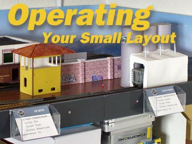
Besides being easy, quick and inexpensive to make, minimum space layouts are often a lot of fun to operate. It’s a well-kept secret that the techniques for running a model railroad can apply just as well to very small layouts as they do to large, $15,000 basement-fillers. This page is dedicated to showing you some ways to enjoy “playing” with your micro layout!
I think there’s a negative mythology afloat in the model railroading world that discounts small layouts as “boring and useless.” These myths are completely false! It’s time to puncture them and throw them away. So another purpose of this page is to deflate the myths and get rid of them, once and for all. Minimum space layouts are one heck of a lot of fun. Let’s kick back and enjoy them!
FALSE MYTHS ABOUT SMALL MODEL RAILROADS
Here are the misconceptions (or “myth”-conceptions) that bug me the most. They all deal with operating your small layout (if you wish to do so).
- Small layouts are too simple to be any fun.
(This false alarm is easily refuted in “Tuning Fork Layouts Can Really Hum.”) - Most small layouts are just switching puzzles.
(This nonsense is exploded by our exploration of Switchman’s Nightmare.) - Small layouts can’t be operated like the prototype.
(For those who still aren’t convinced of the ignorance of this assertion, take a look at Patagonia Yard, Phantom Layouts and Sutton Road.)
QED. I rest my case. Let’s get on with having fun! —Carl Arendt
‘TUNING FORK’ LAYOUTS CAN REALLY HUM!
A “tuning fork” layout has one turnout (track switch) that divides the running line into two branches. Chris Ellis gave it the name because it resembles such a fork (at left). Chris is the editor of Model Trains International, arguably the best small-layout magazine in the world. He declared, “The ‘tuning fork’ is the smallest possible layout that provides opportunities for railroad-like shunting operations.” We have a couple layouts in this issue (below) that demonstrate Chris’s point.
Prof Klyzlr, from Sydney, Australia, agrees. Prof declared, “The trick is to stop thinking of it as a modeling display and start thinking about it as a portion of a real railroad. For example, suppose one ‘leg’ is the main line and the other is an industry—a typical prototype situation. The industry track will have several defined ‘car spots’ where cars may be loaded or unloaded.
“This could be as simple as ‘the industry has a warehouse with three doors: the boxcar goes to Door 1, the tankcar to Door 2, and the gondola to Door 3.’ These moves could be somewhat complicated, depending on the sequence of the cars the loco is hauling.
“Or the task might be as complex as: the spur has an end-loading ramp, a cattle pen and a freight shed. The cattle pen can only be served by stockcars; boxcars or flatcars can serve the freight shed; and flatcars are logically the car for the end-loading ramp, but a loco may not be able to fit past the cattle pen. So to deliver or retrieve a flatcar at the loading ramp, a ‘reacher’ car is needed…
“There are plenty of plausible alternative scenarios, and the length of the headshunt/switchback could make things easy, or really, really hard!”
To check out a prototype tuning fork, see John Bruce’s tour of Cranbury Station, New Jersey USA in Scrapbook #82. For some more eye-opening examples of prototype switching at forked tracks, still with only one turnout, see the amazing blog of Jack Hill, from Enola, Pennsylvania. Scroll down to “Stretching a Simple Spur” and “Proto-Examples” to see several pretty involved real-life switching jobs on tuning-fork track arrangements. And finally, here are two excellent model examples (below).
Multi-Mode Fork Switches Both Cars and Nationalities
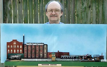
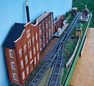
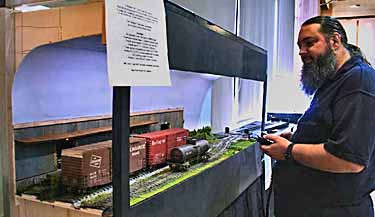
Jim Ronda, from Tulsa, Oklahoma USA (shown at left revealing the depth of his little layout) describes his concept this way: “I wanted to build something that was no more than six inches wide and three feet long. It needed to have locations that could provide interesting settings for my British GWR locomotives and rolling stock and my American equipment. It had to have good operation potential. And it could have no more than one turnout; no traverser and no fiddle yard! The obvious answer was the Tuning Fork.” He got the original plan from Chris Ellis’s book, Next Steps in Railway Modelling (page 30).
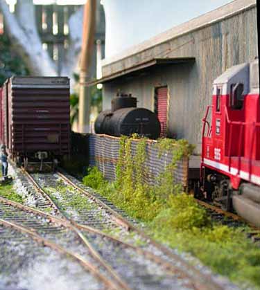
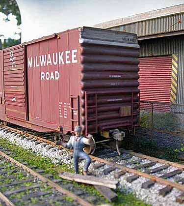
Using 16.5mm track and careful selection of scenery structures, Jim managed to create a layout that can be operated as British OO scale or US HO scale simply by changing the signage and a few accessories. It’s called Rockford Junction (upper left) and Britannia Sidings (upper right). As for operation, Jim writes, “I have a traffic sequence for each location and have car cards for every car. All of this has been great fun… After about a week of operating with a modified card order system it became clear that I needed to add a single track fiddle yard extension. I’ve done that now—a three-foot-long detachable extension to allow cars to enter and exit. That seems to work quite well.”
‘Accidental’ Fork Layout Turns Out To Be Lots of Fun
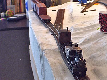
John Gardiner IV, from Provo, Utah, USA, is a teen-age model railroader. He moved to Utah last fall, brought along his plans for a 3x9ft HO layout, negotiated space for it, and began work. Then a strange thing happened.
As John tells it, “I began laying the first flextrack. When I noticed that my first four feet of operational track looked vaguely like an Inglenook layout, I dove into the box of salvaged items and grabbed a few cars. I threw them onto the layout (what little functional part there was of it) and started switching. The object was to arrange the cars so that all but one would be on one spur, while the other, a track cleaning car, would be on the second spur, cleaning the track. But I also had to make sure that once I was done I could easily exchange the Kadee logging car kits for the track cleaning car, and so end with the locomotive and logging cars on one track and the other cars on the second spur. I had a blast!… [This semi-layout] is absolutely miniscule in size, and it is still astonishingly fun.”
The moral: if you think about them carefully, even very simple layouts can be a lot of fun to operate!
SWITCHMAN’S NIGHTMARE BECOMES A PROTOTYPE DREAM
[NOTE FROM CARL: I received an e-mail recently from Gary Miller, who lives in Livonia, Michigan USA. He’s exploring small layouts and has built a combined Timesaver/Inglenook on a 48x18in (120x45cm) shelf; now he’s looking at the Switchman’s Nightmare layout (found in our Classic Layouts honor roll). He was asking me what the initial car positions and “rules of the game” are for this layout, because they’re not listed anywhere on the internet.
Gary was hooked by the widespread myth that all small layouts are switching puzzles. Not so! I believe that like any model railway, small layouts are condensed versions of real railroads (or something very similar that’s freelanced) and can be operated much like the real thing. That’s a big part of the fun. So I sent Gary the following response, which was a bit more than a reply to his query! The response is keyed to a redrawn version of Linn Westcott’s original layout, preserving Linn’s labels for each of the layout sections.]
Switchman’s Nightmare is a genuine railroad layout… It is a compressed version of prototypical trackage, and can be operated like a real railroad in almost any way you choose… You can apply to this layout any or all of the multitude of Operating Systems available.
The key operating element for a small layout is the Car Routing System. This can take many forms, but basically it is a way of identifying the destination and next move for each car on the layout. Whether you use “Car Cards” or roll dice or identify logical spots, or whatever, you’ll need to follow several specific steps to set up a CRS-type Operating System:
1. Identify the purposes of the tracks on the layout. In the case of Switchman’s Nightmare, you appear to have two yards for sorting cars—Eastbound (Alpha) and Westbound (Beta), as well as a small industrial switching district (modeled in low relief along the back).
2. Figure out what kind of traffic you’re going to run. In this case, you’ll have arriving freight trains and departing freight trains, as well as intra-yard transfer runs and a local switching turn. That’s four kinds of trains you’ll be able to make up and dispatch.
3. Set up your CRS (Car Routing System). There’s an example in the next section (Patagonia Yard), and there are a great many others — do some research. Try searching online for “model railroad car routing system,” and any other combination of words that makes sense to you.
4. As part of the CRS, you will need to select a destination (or series of logical destinations) for each car. The list can include: Eastbound Yard – Track #1 (Arrival), Eastbound Yard – Track #2 (Departure), the same pair of tracks for the Westbound Yard, and a listing for each industry found in the Switching District (there’s room back there for four or more customers—two alongside The Trap and at least two more to the right of the turnout).
5. So… you’re ready to go. Place an “arriving train” on Eastbound Yard (Alpha) – Track #1 (Arrival). Find the cards (or whatever you use) that indicate a destination for each car in the train. Some of them will go to Departure tracks, others to industries. Those cards are your switchlist for the first train. It can be either a transfer run to the other yard, or a switching turn (depends on how many cars are going to each place. A “train” here will no doubt be at most four cars long!)
Now, imagine that your train has just arrived on the Arrival Track. Cut off the loco and move it over to the servicing track (behind Alpha Yard). Bring in a switcher and make up the first train. Then attach a loco and send it out on the road! [Big deal. It moves over to the yard lead, then backs over the switch up to the runaround track, which it uses to take cars either to Beta Yard tracks or to the industry tracks, depending on which train it is.) At the industry tracks, there may be empty cars waiting for pickup (which you have cleverly placed there), so you take them along as you return to the Eastbound yard.]
By now, another train has probably arrived at the Westbound yard arrival track… and you go through the same process with it. At this point, things are getting crowded and possibly clogged, so it’s time to send a train out on the road (away from the yards). Collect the cars from one of the departure tracks, attach a loco, tack on a caboose (if that’s your era), blow the whistle, and depart (i.e., remove the cars and loco from the tracks).
And so on.
You can get a lot more formal than this if you wish (schedule train departure times in advance, use “situation cards” to create various diversions like “loco drops a rod in transfer track; wrecking train needed,” etc.). There are lots of other ways to view your trackage, too… for another approach, you might check out Scot Osterweil’s classic switching layout, Highland Terminal, elsewhere on this site.
You’re only limited by your imagination! One possible improvement might be to put a fiddle yard (perhaps a 24-to-36-inch cassette) on the right hand side, connected to the Alpha Yard lead track. That way, trains can actually depart from the layout and be removed by putting the cassette on a shelf and connecting a replacement cassette, loaded with new cars (or by emptying the first cassette and refilling it with new cars). This configuration is shown below, attached to another drawing of Switchman’s Nightmare using Peco Code 83 trackage and #5 switches.
EVERYTHING YOU EVER WANTED TO KNOW ABOUT CAR ROUTING
All operating systems have two main parts: Scheduling Trains and Routing Cars. Small Layouts, which usually model only one or two stations, have less need for Scheduling methods (although there are exceptions—see Sutton Road below). Most minimal layouts focus on Car Routing systems… ways to specify the destinations, contents, and purpose of every car on the layout as a guide to gathering, marshalling, and then distributing (switching) them to customer locations.
Car Routing systems vary widely in complexity and sophistication, from Paul Boehlert’s paper-free Blindingly Obvious Car Routing (BOCR) system to basic paper (or computer) based methods, such as the widely-used system offered by Micro Mark (their instruction sheet is well worth reading). On this page, we’ve illustrated several more Car Routing systems particularly useful for tiny layouts and tried to refer you to others. Some Googling will locate still more, and we apologize if we accidentally left out your own favorite!
Patagonia Yard Illustrates a Good Car-Card Routing System
Patagonia Yard is a 130x50cm (51x21in) HO layout based on a Southern Pacific branch in Arizona USA and built by Marcelo Szkatulak, from Toledo City, Spain. It was described in Scrapbook #36. Marcelo acknowledges borrowing a number of planning ideas from this site, including using hidden sector plate and traverser tracks (plan below). The pike was designed for operation, to exchange cars among the Cargill Plant (a), Patagonia Depot (e) and The Route (Main Line), (labeled c). Marcelo describes his operating system this way.
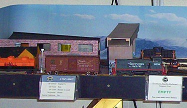
“I have several 40 foot cars (box, tanks, covered hoppers, gondolas, etc.) and little shunters to manage my operation sections. I work with two little locomotives, a GE 44 tonner and a GM SW1500. I have a card for each car in the layout (so far I have tested it running eight cars at time). Each Car Card (examples shown at lower right) lists the car number, owner´s name, car type, what movement should be made if the car is loaded or empty, and special features—some cars should not be ‘bumped,’ for example, or the cabooses need go to a ‘caboose track,’ which is an exception in the RIP track (b) for this kind of car.
“I also have a lot of general Movement Cards that tell me what movement to make for a selected car (examples below). The cars can be in Patagonia Depot, in the RIP track or in the c line (also called ‘Route line’). In each movement card there are messages like ‘Empty,’ ‘Load’ or (the best of them) in red ‘COUPLER DEFECTS Go RIP TRACK’ or other troubles.
“In operating, when I select a Car Card, I also take a Movement Card. After the movement of the car both cards are placed at the end of the box. The Movement Cards can also be shuffled. In the RIP Track when there are two cars I generate a special movement to take out one of them using a Movement Card in the usual way.”
[ANOTHER NOTE FROM CARL: Marcelo’s Car Routing System has all the ingredients needed, along with a few extra tricks of his own. Car Cards are a nearly universal way of keeping track of the rolling stock, and selecting cars to switch can be as easy as pulling cards from the deck. Other systems use more complicated methods, some even generate “needs” lists for the shippers on the line, requesting the type and number of cars they need during a typical week or so. You could also have your computer randomly select cars from a master list, or you could print out the list, then close your eyes and stab a few names with your finger.
Marcelo’s Movement Cards determine where the car goes. There are lots of other ways to decide on destinations. For example, many systems put a list of potential destinations on the Car Card and move the car to each one in turn, keeping track by making pencil ticks on the card or sliding a paper clip down the card’s edge. Ian Holmes developed an ingenious system using dice for one of his tiny layouts. There are lots of other ways to determine what the online customers need, and how to select cars from the pool to fill those needs. The net result is a Switch List, that gives the crews on the ground their instructions for the day. How to accomplish the mission is up to them—which happens to be exactly how the real railroads do it!
An unlisted but important ingredient of your system must be an understanding of the flow of traffic on your layout. In Marcelo’s case, for instance, he has clear destinations on the visible layout, and still others offstage, accessed by The Route (c). Presumably, cars from c are hauled away to the big yard a couple miles down the line, where they are processed and will later return with other missions. Marcelo has also chosen to make the RIP (Repair In Place) track a part of his ongoing system—a good idea and an excellent destination for nearly any type of car. Similar versatility is offered by such tracks as interchanges, team tracks, and car ferry or wharf tracks.]
RUN A REAL SLICE OF A RAILROAD USING THE ‘PHANTOM LAYOUT’ CONCEPT
A key to operating realism is the “Phantom Layout” concept, which allows us to operate a slice of a real railroad, just as the full-sized roads do. The Operating Systems we’ve been discussing are tools to help us fulfill this idea.
Prof Klyzlr has articulated this concept beautifully. “It occurs to me that, instead of trying to squeeze the entire North American rail network into a 2x4ft (60x120cm) box, it may just be easier to decompress a relatively accurate scene into the 2x4ft space—choosing a small ‘modelgenic’ bit that challenges the model builder and operator—and effectively ‘stage’ all the other bits. Therefore, we can have all the benefit of activities that may be occurring on segments of railroad tens, hundreds or even thousands of miles away, and still be dealing physically with the consequences of those ‘unseen railroad operations’ on the little bit of the railraod we have modelled!”
That’s the Phantom Layout concept in a nutshell… treating our small modeled scenes as functioning pieces of the whole railroad network. Here’s how Prof illustrates the idea.
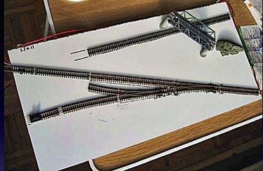
Jacques Bourdouxhe, from Quebec, Canada, posted the plan of his N-scale under-construction micro layout (right), asking how best to operate it. Prof explained, “The issue was that, when limited to the context of only the modeled track arrangement, operations quickly became repetitive, predictable, and very constrained. The layout itself, having only four fixed car ‘spots,’ could only host three cars at any one time, with no physically easy and prototypically plausible way for them to be swapped for other models.
“A combination of some minor ‘staging track’ additions, and a mental ‘connection’ to the rest of the wider North American rail network, provided a context to open up the operations of the modelled section of layout.” The only physical change required to the layout was to extend the spur running to the left edge into an extension fiddle track added on the left.
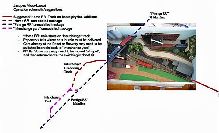
As summarized in Carl Arendt’s article, “Nine Ways to Play With Your Minimal Layout” (Scrapbook #85), “Using the lefthand siding as a connecting track for ‘Foreign RR’ interchange gives Jacques a focus to plan car assignments and train movements. Cars can be routed to spots on and beyond the ‘Home RR.’ The layout develops new purpose, and operations are a lot more fun!”
The article goes on to describe two other applications of the Phantom Layout idea… Carl’s Carnegie Car Shops and Prof’s Brooklyn: 3 AM. Often this broad-scale way of viewing your layout’s mission and purpose can provide a healthy backdrop for a busy schedule of operations.
[STILL ANOTHER NOTE FROM CARL: In this page so far, we’ve been focusing on the Car Routing capabilities of model layout operating systems. They’re the most important ingredient to satisfy our thirst for operations on our minimum-space layouts. But there’s a second operating capability of most operating systems—Scheduling Trains to move cars from city to city or yard to yard, positioning them for pickup by local switching crews. Scheduled trains are less common in very small layouts, because there usually are only one or two stations depicted! But there are several ways in which micro modelers have made use of this concept. The following story shows one of them.]
WANT TO FEATURE HIGH-SPEED LOCOS AND GLITZY EXPRESSES?
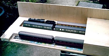
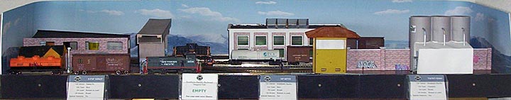
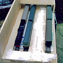
A few years ago, Bob Hughes, from Sandbach, Cheshire UK, built a clever layout around the final few yards of trackage in a busy passenger terminal. The layout was called Sutton Road. It measured 4x1ft (120x30cm) and was featured in Scrapbook #67. The basic idea, pictured above, was to make the visible gap (between the end of track and an overpass view block) just slightly shorter than the length of two passenger coaches (carriages). Thus, when a pair of carriages rolled into view from beneath the overpass, they gave an uncanny imitation of the end of a 12-car express train backing into the station! Further, large express locomotives could readily be used in this setup, looking like arriving motive power attached to a single coach that imitated an entire train length (illustrated in rear track at left photo above).
This illusion-based approach actually works remarkably well, and a variety of layouts designed around it can be found in our Micro Layout Design Gallery. In addition, quite a few variations of these layouts have been devised, including Evenley, by Nigel Beeton; Southwark Park, by Will Ayerst; and Prince’s Cross, by Allen Walker. Allen also created a photo sequence that illustrates the effectiveness of the illusion (included in the article on his layout).
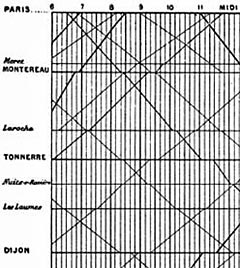
The key to operating a passenger-terminal layout is, of course, the train schedule… AKA the Timetable. At the right is shown a portion of a French timetable of the 1880’s representing trains between Paris and Dijon from 6 am to Noon. Stations are listed in the left-hand column, spaced proportionately to the actual distance between them. Hours of the day march across the top. Each line on the graph is a train, with faster trains having steeper slopes. Lines running upward from the left represent trains approaching Paris. Lines leading downward to the right represent departing trains. This diagram shows the whereabouts of every passenger train on this portion of the line at any given time! It provides a superb basis for the Phantom Layout timetable of our railroad.
Suppose we are building a model of a terminal in Paris. We can read across the line beside Paris, and see immediately that we can expect arriving trains at 6:55, 8:15, 8:30, 11:20 and 11:50 AM. We will be dispatching trains from the terminal at 6:30, 6:50, 9:00 and 11:00 AM. Now we can easily make our terminal’s operating plan and see how it fits into the rest of the railway system. For more information and an excellent tutorial on building timetables for model railroads, see Mike Dodd’s wonderful website. It’s well worth a careful reading.
If you want to keep your operators on their toes (and boost their nervous energy considerably), then buy or build a “fast clock” that registers an hour in, say, five minutes… and run your timetable by the clock. Because shunting and train marshalling take roughly the same amount of time in model form as they do in real life, your crew (or you) will get a real workout to keep “on schedule!”
Bob Hughes chose a more relaxed format to operate Sutton Road. He created a Sequential Timetable, where trains are assembled and dispatched or received in sequence, regardless of how much time is required. So no one ever gets behind or has the unnerving experience of being told they’re “holding up the entire division.” Bob provided us a sample sequence, with all moves written out in the order they’re to be performed. Included are such moves as freeing a newly-arrived locomotive to visit the service tracks, shunting empty coaches into available platforms for passengers to board, and the like. Bob’s illustrative sequence is reproduced below (platforms are numbered from back to front).
SUTTON ROAD SEQUENCE TIMETABLE (Excerpt)
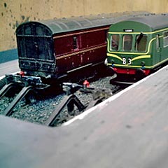
| To start the sequence: Platform 1 – empty. Platform 2 &ndash DMU (push-pull multi-unit railcar). Platform 3 &ndash 2 coaches (tail end of train ready to depart). 1. DMU departs Platform 2. 2. Train arrives Platform 1 (Steam loco+coach). 3. Station pilot (unseen) propels 2-coach train into Platform 2. We now have loco-hauled trains in all platforms: arrival in 1, departures in 2 and 3 (as shown in upper left photo). 4. Train departs Platform 3. 5. Station pilot (again off stage) removes coach from Platform 1. 6. DMU arrives Platform 3. 7. Loco in Platform 1 departs, running light. This leaves platform 1 empty again, with a 2-car DMU on 3 and the coaching stock waiting to depart from 2. 8. Another DMU arrives on Platform 1. 9. Coaching stock departs Platform 2. | 10. DMU departs Platform 3. Station now empty apart from the DMU on P1. 11. Main line diesel arrives Platform 2 with coach (implying an express train). 12. Station pilot shoves Baggage Car into Platform 3 , departs running light. 13. DMU departs P1. 14. Station pilot (unseen) removes the coach from Platform 2. 15. DMU arrives on Platform 3, stopping short of the Baggage Car which is still there. 16. Station pilot (unseen) propels 2 coaches into Platform 1. 17. Diesel from move 11 departs light from Platform 2. State of play now: Baggage and DMU in Platform 3, Platform 2 empty, Platform 1 train awaiting departure. 18. DMU departs Platform 3. 19. Railcar arrives Platform 2. 20. Station pilot arrives Platform 3, departs with Baggage Car. …And so it goes on at this busy passenger terminal! |
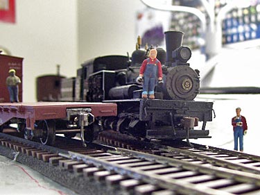
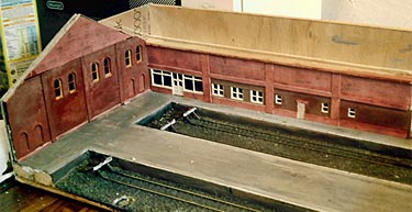
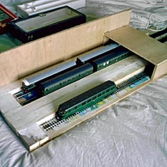
These operations represent perhaps two scale hours of a day’s work at this busy model terminal. The photos below show candid shots of a similar operating session taken during layout construction. The sense of actually “running a railroad” is a delight, even before the scenery is in place!
[HINT: Real railroads keep similar timetables for freight trains, and this system is fully applicable to freight yards of almost any description… and not just to terminals, but also to locations that receive trains from several directions. Consider Montereau in the French timetable above. Or try this system on Switchman’s Nightmare!]
BREAKING NEWS: Today (1 Nov 2010) marks the premier of a new podcast, The Model Railway Show, a fast-moving and professionally-produced biweekly audio look at the State of the Hobby. The first show includes a brief interview with Carl Arendt about this website! You can hear Show #1 here.
Leave a Reply