PAGE 44 – DECEMBER 2005

Conventional wisdom has it that switching layouts,
especially those arranged in a straight line as on a shelf,
MUST have a runaround loop (passing siding) in order to
serve spurs facing in both directions. Here are a few
examples of layouts without runaround facilities. They’re
interesting, ingenious, and sometimes inspiring. Take a look!
AT LAST … A PASSENGER INGLENOOK!
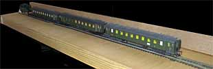
One way to avoid runarounds on your shelf is to arrange the sidings to face in just one direction. This is the strategy of the classic Inglenook switching game (described in our Micro Layout Design Gallery). Now David Thomas, from Greenford, Middlesex England, has designed a micro Inglenook — under four square feet in area — that can handle five-car express passenger trains!
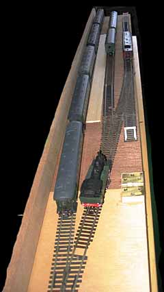
Working within the constraints of a micro layout format, David designed a folding baseboard that, folded, measures 52x10in and unfolded, 104x5in. The 104 inches of length allows a full 5-3-3 Inglenook pattern with a long siding that holds five full-length passenger carriages (coaches)! David mocked up the design (see photos) using a Peco medium radius turnout on the “main line” and an unusual long-radius one to the short sidings. Long passenger coaches look much better on long, gentle curves, and this turnout combination works on a micro layout without a space penalty! David had this to say about the important points of the design:
“1. You can have the fun of shunting a longish passenger train in a micro layout space.
“2. If you’re dealing with long passenger stock then medium and long points won’t look silly, short ones probably will.
“3. Making up trains with the stock in exactly the right order may be more prototypical for passenger operations than for freight trains. The restaurant has to be between the first and second class sections; coaches bound for the same ultimate destination must be marsalled together; you can’t put the baggage cars in the middle of the train; the postal car has to be at the front; and train make up might well change on different days according to loadings.
“4. You are probably making up two trains, the ongoing express and the shorter train carrying through coaches up a branch.
“5. Including the station platforms makes it more exciting than just a set of carriage sidings. This model can easily be one end of a longer station — you just don’t see the other ten carriages.
“6. In a city location retaining wall backdrops [represented in the mockup by backdrop boards] are entirely prototypical, and this folding arrangement creates an open box.” You can add a lid to the box and easily have a self-contained travel bundle.
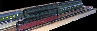
On top of all that, David added a loco servicing spur to the design based on his mockup — still retaining an area of less than four square feet (below). This spur provides a place to show off your best road locomotives while the shunting is proceeding. One last word of advice from David: if you decide to build this layout and can afford a bit more space, leave wider margins at the edges of the table — so if a train is accidentally derailed, it won’t plummet all the way to the floor!
A TRINITY OF FORKS
Slightly simpler than the Inglenook is the plan that Chris Ellis, editor of Model Trains International magazine, has dubbed “The Fork”. Although the switching is somewhat limited, well-planned scenery can make these little lines a pleasure to have around — and they’re portable enough to take to parties!
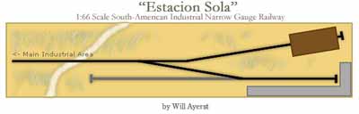 Estacion Sola is a Fork layout being constructed by Will Ayerst from London, England. Though there’s a kickback siding (shown in gray on the plan), Will is modeling it as an abandoned spur, so the active trackage is a true Fork pattern. Will comments, “I’ve decided to go with 1:66 scale to get a 600mm (2ft) track gauge to model the loco shed and worker drop off point of an industrial narrow gauge railway somewhere in South America.”
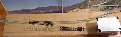 Construction has just begun; trackage is Peco with some ties removed. We’ll look forward to receiving more progress reports from Will. By the way, he’s 20 years old, and this is his first 9mm gauge railway.
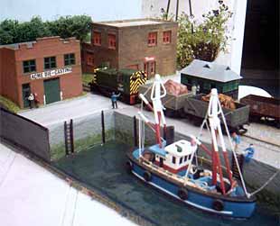
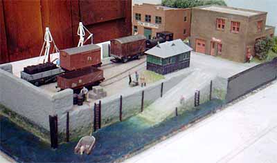 Port Abel is a very small OO scale layout built by Bob Hughes from Cheshire, England. Measuring only 2x1ft (60x30cm) with a 24x6in (60x15cm) fiddle yard, the line represents, according to Bob, “a rail served quay with a single track coming on stage between two buildings and splitting into two spurs. The loco propels two or three wagons onto the pier and swaps them for any wagons already there.”
The layout, in common with Bob’s Green End Quarry (pictured in Scrapbook issue No. 41) , is built from scrap wood picked up while he was driving a delivery van, and the name is “an awful pun.”
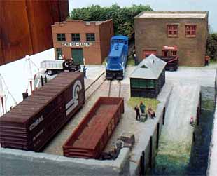
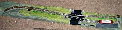
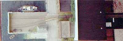 As you can see from the aerial view, Port Abel is a Fork design. Bob also designed it so it could be used with either British or American rolling stock, as illustrated below. For more, see Bob’s website.
 Sidetracks is a Z-scale Fork line that measures 60x7cm (24×2.75in). Alan Cox, from Swansea Wales, built the little layout while he was supposed to be writing his thesis, and thus the name!
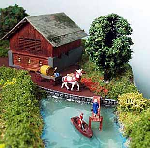
Using a wooden base from an old test track, Alan spread lightweight filler to make scenery and then
laid the track back into the still wet filler on bendy plastic strip. After painting with homebase matte camouflage paint, the track was ballasted, rust painted on the rails and scatter material added. The signal is an old Märklin unit, manually controlled. As the second photograph shows, a railbus is used for motive power, and a tall embankment on the near side allows it to hide away between visits to the onstage scene.Alan really likes tiny layouts — his next project is to model an underground (subway) station in a cardboard mailing tube! <g>
A TRIO OF KICKBACK SIDINGS
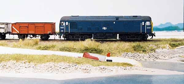
 Shell Island is a minimum space EM gauge (4mm scale, 18.2mm gauge) layout built by Neil Rushby from York, England. It portrays the Cambrian Coast in British Rail days between the late sixties and early seventies.Neil has used skillful weathering and well-observed scenery to depict very convincingly a somewhat barren stretch of wind-swept coastline. The layout was featured in the August 2003 issue of Railway Modeller magazine. Neil’s photos convey something of the feeling of the line, which measures just 30x15in (75x38cm), with a 24in three-road sector plate in the fiddle yard. For more information and photos, see Neil’s website.From a layout design standpoint, adding the kickback siding to The Fork increases the switching complexity and requires careful planning of car (wagon) arrangements in the fiddle yard to enable the switching loco to serve all the sidings.
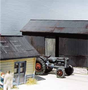
 Location X was designed by Colin Peake, from Nottinghamshire England, based around part of a narrow gauge railway serving a Ministry of Defence establishment in the UK. The line carries supplies and personnel around the military establishment. Freight is delivered to the kickback siding, and passengers alight at the station platform. Colin has suggested an unusual view block to help conceal the “exchange siding” (fiddle area) from view — a length of standard gauge track with a line of rusting four-wheel vans typical of MoD depots up to the present day. One scenic element that should add to the visual appeal are the high-security fences separating different areas of the site, giving a real air of security and perhaps mystery as to the exact nature of the work going on here!
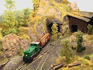
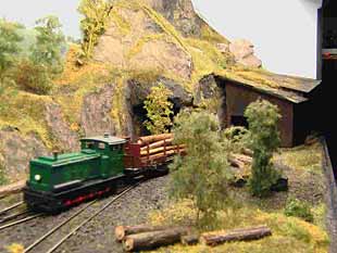
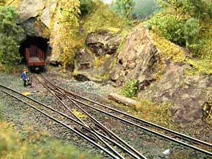
Peter Hoffmann, who lives in Brunn am Gebirge near Vienna Austria, used the same track plan but concealed the right rear spur to represent a tunneled route up the mountain to the forest for timber. His HOe (1:87 scale on 9mm track) logging railroad, Petey’s Sawmill, measures 100x30cm (39x12in) and is fully automated. The following photographic sequence traces the operating cycle and reveals some of the secret mechanical magic performed inside the mountain.
 s
s(Above left) Peter’s scratchbuilt lokey arrives from the forest, emerging from the tunnel with a load of logs for the sawmill — the brown building at the right. (Above right) After clearing the switch, the loco backs its loaded car into the front siding and on into the sawmill.
Our secret camera now reveals the machinations that are hidden inside the mountain! (Left) The loaded car arrives inside the mill, and the load is grabbed by a mechanical arm. (Center) The arm lifts the load clear of the log car. (Right) The arm moves the load over to the rear track., inside the tunnel entrance.
(Left above) The loco pulls the now-empty car out of the sawmill and forward to clear the switch. (Right) Reversing, it begins the long climb back up to the forest (by way of the tunnel).
PERPETUALLY BUSY INDUSTRIAL RAILWAY
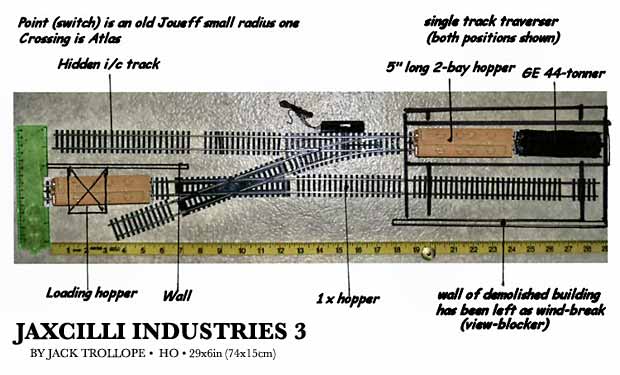
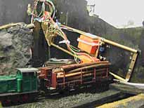
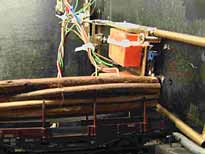
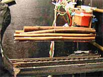
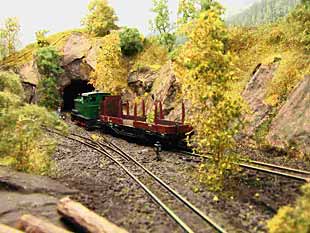
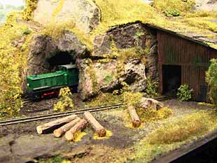
Jack Trollope, from the Highlands of Scotland, has designed yet another of his busy industrial lines. Third in the series, this one is called Jaxcilli Industries 3. Total rolling stock of the line comprises two 36-foot covered hoppers (each about 5in. long) and a GE 44-ton switcher. Jack describes the complex operation, worked out on a track plan of his own devising, this way:
“Basically:
1. Car is pulled from hopper and dropped just in front of traverser, clear of the crossing.
2. Loco moves via traverser to top track and pulls inbound car from hidden i/c (interchange) track.
3. Turnout is thrown, and car is pushed onto crossing and dropped.
4. Loco reverses onto traverser (switch is thrown) and traverser moves to bottom track.
5. Loco picks up loaded hopper, pulls it onto traverser, traverser returns to top track.
6. Loco pushes car to hidden i/c and drops it.
7. Loco reverses to traverser, point is thrown and inbound car is picked up.
8. Traverser moves to bottom track, loco pushes empty car under hopper.
9. Loco returns to traverser.”
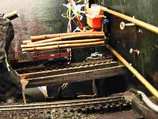
Got that? Needless to say, the loaded car — now hidden away in the interchange (fiddle) track — is unloaded by hand, while the empty car now spotted under the loader is being filled. Then the cycle repeats. This very tiny line provides a whole lot of continuing action in a very small space!
A NEW USE FOR YOUR EASTER EGG BOX
Inspired by the shoebox layouts featured elsewhere on this site, Anthony Bilton from Sheffield England, has devised a complex, very operational layout in a space of about 14x5in (36x12cm)! As Anthony tells it, “I got a chocolate egg for Easter, from my wife, that came in a box through the post. The egg was delicious, and the box seemed too good to throw away. The front opens up and over and the construction is strong and robust. As a result the layout will fit snugly in the box with cutaways at the front for viewing and rear for stock replacement and movement of the sector plate.”
Anthony’s OO9/HOn30 mockup (above left) and his construction progress (right) with track in place and structures beginning to take shape show the layout’s form and promising appearance. “But what,” I asked Anthony, “about operations in this complicated knot of trackage?” Here’s his reply, which delighted me:
“The layout will represent the buildings end of a small limestone quarry/cement works. The very rear line and sector plate represent the rest of the network and are hidden from view by the large brick building and small retaining wall. Quarried items arrive in dumpers and are shunted into the covered track with the lean-to (right rear). These are exchanged for empties (through a hole in the backscene) and are then shunted away to reload.
“Full flats of cement bags will be brought from offstage across the pointwork with two reversals and end up on the front right line being unloaded and stored in the shed at the extreme right. Full dumpers of quarried stone also arrive at the same siding after the two reversals to dump stone in the barge at the front. The quayside is yet to be modelled, but will be detachable and stored in the box.
“Finally there is some coal traffic from the traverser to the front left siding and rail fed boilerhouse (large blue door at the left). This is occasional as the wagons will block the main siding entrance.”

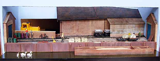
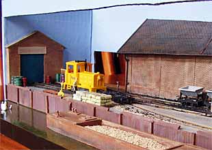
A MICRO PORTAGE LAYOUT
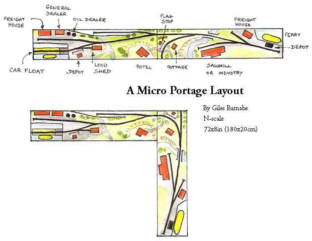
By Giles Barnabe
This plan has been inspired by two articles in Model Trains International, a British modelling magazine specialising in small layouts. Past issues have dealt with the narrow gauge Portage Railway from Canada and also its US equivalent the Marion River Carry Railway, which was standard gauge.
Like its Canadian counterpart this line connected two bodies of water, in this case by-passing a section of un-navigable stretch of river, but here the route was only three-quarters of a mile long. The nearer end was Lower Steamboat Landing where a tiny car-float connected with the railhead on the far side of Raquette Lake, so the occasional freight wagon could appear on the line. The far end of the line served a riverboat quay (Upper Steamboat Landing).
Apart from meeting the scheduled ferries, the trains ran on demand — one could ring the depot and a short while later the train would arrive to take you down to the end of the line, all for a dollar. The “varnish” was supplied by old horse tramcars, one of which had had its seats removed to act as a baggage car. The only motive power was a small four-coupled Porter saddle tank.
Accompanying the article in MTI was a layout suggestion for H0 scale, and these ideas are an expansion of this but in N gauge to fit the entire line into an area of 576 square inches, thus qualifying as a Micro Layout. The two boards each measure 36×8 inches and can be arranged in a straight line or L shaped, which may be an advantage if home space is limited. I have added a bit of track to make operation more varied than
on the original, where freight cars were left on the main line to be loaded or unloaded.
The model version has a siding hidden behind Lower Steamboat Landing which can be deemed to serve a quarry or sawmill, thus loaded cars can appear and be worked across the lake on the car float, which can carry two cars at a time. There is also a siding by the car float serving a couple of local businesses and a fuel dealer. The original line ran near a local hotel, and this has been included on the model with its own tiny flag stop.
In the layout’s “straight” mode, this provides a place to park the passenger stock while a freight train is running. At the other end of the line there are two freight sidings, one serving a quayside freight house, the other an industry that could be a dairy or something connected with the lumber industry if the hidden line is a quarry. Instead of the horse cars one might use an ancient combine or drover caboose for passenger traffic.
As the real line closed in 1929 this is a period piece; you’ll need to use a Little Joe or 0-6-0ST if you favour steam power, though given the industrial additions you might be able to convince yourself the line lasted into the 1950s and run a small diesel switcher instead. The curve on the “branch line” is five inch radius, horribly tight, but just about possible if speeds are slow. Without the need to be a true Micro, you could widen the boards to gain more room for scenery and make the curve up to eight inch radius which would enable you to use Minitrix R1 curves.
References: Model Trains International no. 50
Narrow gauge & Short Line Gazette Jan/Feb 1994
Ed. Note: I hope you’ve enjoyed looking at these unusual
and interesting layout plans — all without runaround facilities!
Please let me know if you’d like to see more such “tutorials” on
various types of small layouts. Just click on “Contributions” below.
I’d like to contact Chris Gilbert de next ne of his designs. Is that possible?