PAGE 73 – May 2008
[vc_row][vc_column width=”1/1″][vc_column_text]
H O T I D E A S F O R S M A L L R A I L R O A D S
Among the most popular features in these Scrapbooks are articles about
real railroads (also called “prototypes”) that can be converted into excellent
models. We’ve had a couple of good prototype articles recently (in Scrapbooks #67, #69
and #72a), and they have invoked a response from several readers to share
some additional prototypes. So here a group of real railway scenes
that would make excellent small-layout models!
CAR REPAIR SHOPS—A RAIL PROTOTYPE THAT USES TRACKMOBILES!

By Carl Arendt
In Scrapbook #30a “Rip Traxx” (pictured in title photo above) provided a track plan (right) and an operating description of a car repair shop (also called a RIP track) where he was employed on a western U.S. railroad.

In the model version of this yard (at right), Rip replaced the East ladder track with a transfer table, which takes far less room, and focused attention on the West ladder where most of the action occurs. Using “selective compression,” he reduced the number of tracks in the facility as well. To shrink this model even farther and create a micro layout, I decided to model just the portion within the purple boundary shown on Rip’s plan. That is, I retained the transfer table and modeled three through tracks at the East end of the car shops. In all, this micro layout takes up 8½x11in (216x280mm) of space—the same size as a sheet of U.S. letter paper! A small fiddle yard behind the scenes occupies another 8½x8in (216x203mm). If we add in the “transfer table” (2x12in or 50x300mm), the total area required by this tiny car repair facility layout is only 1.2 square feet (1173 square cm)! Yet the operation retains nearly all the flexibility of the original (but adds a fair amount of fiddling behind the scenes to make up for lack of trackage). It’s all made possible by the tiny Trackmobile.
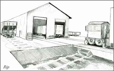
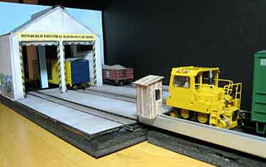
Why did I choose to model the East end of the repair shop? Partly because it occupies much less space than the large West ladder track due to the use of the transfer table. But also, Rip provided a pencil drawing of the East end of his proposed model (below left), and I wanted to try to reproduce that scene using my new Trackmobile model. The result is shown below at the right… not a bad likeness, I think!
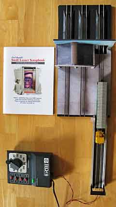
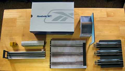
I designed this little layout, Carnegie Car Repair Shop, to make a playground for the Trackmobile. It’s my first HO layout in about 35 years! The overhead view (left) shows the whole layout—the visible, gray part is the size of a sheet of U.S. letter paper (as is my book, shown for size comparison). The transfer table or “traverser” is a Peco Loco Lift cassette with a little window dressing added.
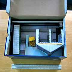 The whole layout breaks down into a few elements (above right) that will all fit comfortably into a Reebok shoe box (right). I will be able to pack about five freight cars plus the Trackmobile and all of the layout elements in the one box for transport. The power controller will travel separately. I’m publishing these few photos of my Work in Progress to get your juices flowing with creative ideas about micro layouts that are now made possible by this very small, very attractive Trackmobile model. Write down your ideas, and enter them in the Trackmobile Layout Design Contest! Deadline: 31 May 2008.
But there’s even more that can be done with this tiny layout. Rip Traxx pointed out that using a rail car mover was a standard way of operating in the shop where he worked. But it wasn’t the only way. Rip reported, in a previously unpublished note, “I have seen an SW-10 spot cars, we spot cars with Trackmobiles and, if the load is hot enough, road power with three or four big EMD’s will spot a car straight from a train, so we could get to it faster. I have seen an intermodel train leave from the RIP track with one car—yes, a one car train. It was that important.” So there’s plenty of operation available—and even room for some Big Power—on this tiny layout!
Don’t miss your chance to enter our first layout design contest!
The goal is to design a micro layout suitable for using the Trackmobile shown above.
No purchase is necessary. See full details on the Contest Page!
POPULAR PARKS PROVIDE PERFECT PROTOTYPES
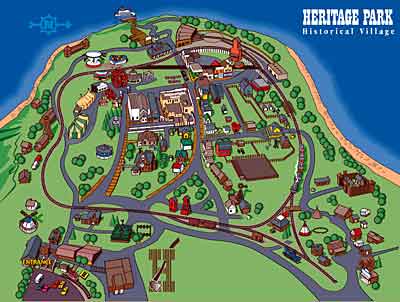 Derek Smith, from Yakima, Washington USA, was inspired by last month’s discussion of prototype pizzas (at museum railroads) to write about his experiences with continuous prototype layouts at Canadian parks. “There are three Canadian sites I have visited that include a railroad as part of their operations,” Derek wrote. “One is Heritage Park Historical Village in Calgary, Alberta. This site has a circle of track around the park plus an engine house, along with several historical town buildings, small vintage theme park rides, and a paddle-wheel stern wheeler boat operating on the adjacent lake. (See map of the park at right. Diagram courtesy of Heritage Park Historical Village.)
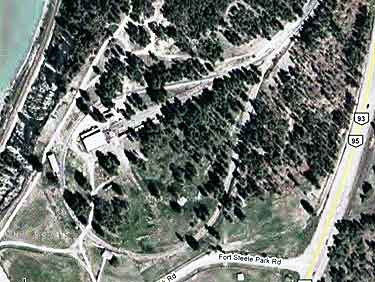
“The second site is Fort Steele in British Columbia. It is a frontier-themed village with a dogbone trackplan with a regularly-operating steam train. The map (below left, courtesy Google Maps) shows the lower loop of the dogbone.
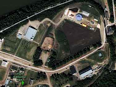
“The third site is Fort Edmonton Park. The map (lower right, also a Google Map) shows the eastern loop of this park’s dogbone, along with the return loop and car barn of a trolley dogbone that also operates in the park. Although not specifically railroad museums, these three sites and their attractions could offer great modeling opportunities. Maybe I’ll actually build one someday!”
LIVORNO PORT TRACKAGE SPARKS MODEL IDEAS
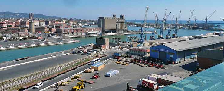
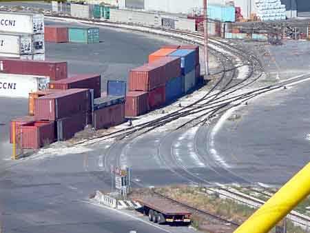 Kevin Payne, from Sussex, U.K., took these photos of dockside trackage at Livorno, Italy, from the top deck of a cruise ship as it approached its berth. Kevin commented, “The attached pictures are interesting, as they show some features that would be really helpful on a dockside micro layout. One of them (at left) is pretty close to being the prototype for the Juster Yard design on your site.”
Notice also that the three tracks curving from the center to the lower right of the photo form an excellent prototype for a corner Inglenook layout. And the pile of containers makes a perfect prototype for an excellent view block in a dock scene. In the scene below, the cranes are delightful, and the warehouses and their yards are full of interesting details for the modeler.
THINKING BIG: HERE’S GRAND CENTRAL TERMINAL IN A MICRO LAYOUT
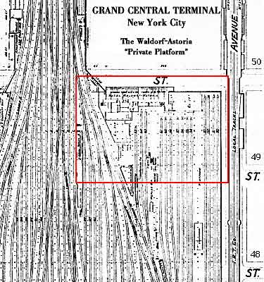
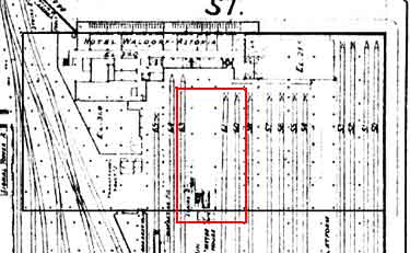
Grand Central Terminal (Upper Level at left) houses a hidden platform for the Waldorf-Astoria Hotel (above). A three-track portion makes a micro (below). 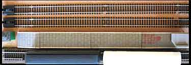
On days when I feel like emulating Commodore Vanderbilt and creating a railroad, my thoughts sometimes turn to the Commodore’s greatest creation—New York City’s Grand Central Terminal. What a modeling challenge: 67 underground tracks hosting 510 trains a day, carrying (in its peak year of 1946) 65 million rail passengers! But as I’m a builder of micro layouts, I sort of put this idea aside.
Then I discovered, on Joseph Brennan’s marvelous website, a little-known fact: in a remote corner of Grand Central, on the Upper Level directly beneath 49th and 50th streets, there’s a private platform and an elevator (lift) rising to the Waldorf-Astoria Hotel directly above. You can actually see the tracks and train-car roofs through the sidewalk grills on 49th Street. In the closeup diagram (top right), the black rectangle is the footprint of the hotel, which occupies the entire block between Park and Lexington Avenues from 49th to 50th Street. The Waldorf platform is the open space between Tracks 61 and 63. The elevator is at the lower center of the diagram, along with a stairway to the street. Amazing!
The micro layout plan is pretty obvious (above, lower right). It’s 8¼x23½in (210x594mm), just long enough to hold two passenger cars (carriages) that are switched in and out via a fiddle cassette on the right, giving the impression that much longer strings of coaches are occupying the full track. This is the same track plan as Bob Hughes’s Sutton Road layout in Scrapbook #67, and the operating scheme would be very similar to the one shown there.
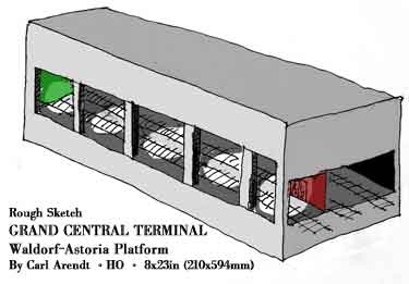 The rough sketch at left shows the idea. In the space of two sheets of A4 letter paper we have a corner of Grand Central station. It’s underground, so there’s a low roof with plenty of pillars, piping, and platforms. A picture-frame proscenium opening reveals pools of light from overhead fixtures that relieve the gloom. The elevator, occupying a former steam power station shaft, is at the right and conceals the entrance to the fiddle yard. The dramatic lighting would be combined with an ambient sound track that features arriving and departing trains constantly thundering by (the terminal throat is right next to this location). The total theatrical experience should provide the viewer with an exciting sense of actually standing inside the immense Grand Central Station at rush hour! All this in 192 square inches (1.3 square feet)!
Another thought: how about a low, motorized platform where viewers can stand and experience the rumble and vibration as the Twentieth Century Limited lumbers past, bound for Chicago (but hidden behind the scenes)?
HAULING CANAL BOATS OVER THE MOUNTAINS
APRR Photos by Carl Arendt
One of the more incredible chapters of railroad history in the U.S. is represented by the Allegheny Portage Railroad in central Pennsylvania. Built in 1832 and abandoned in 1856, the APRR carried canal boats and barges over the summit of the Allegheny Mountains, creating a “water link” between the Susquehanna and Ohio Rivers. The railroad literally carried canal traffic up and over the mountain! It was a critical link to get passengers and freight between the U.S. East Coast and the Western frontier—from Philadelphia on the East Coast to Pittsburgh, the gateway to the West.
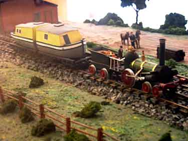
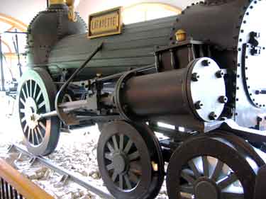
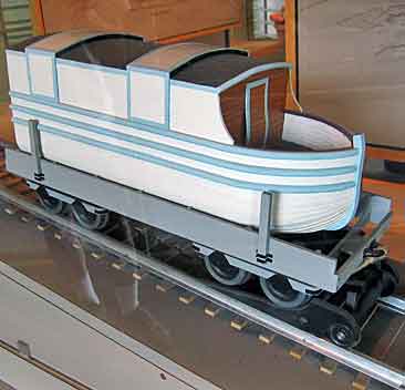
The railroad consisted of 10 inclined planes (funiculars) that literally rope hauled the boats on railroad cars up the steep mountains—they were pulled along the stretches between inclines by horses and later by locomotives. Pictured (above left) is a working model, at the National Historic Site museum, of an early train hauling a canal boat that is split in two and carried on two flat cars. The boats were clearly designed expressly for this journey. The locomotives were early models like the Lafayette (above right) that is preserved at the historical museum.
This amazing feat of railway engineering would be a challenge to model, but what a spectacle: tiny steam lokeys struggling to haul large canal barges, then placing them on inclined planes to be hoisted to the next level (see below)! A couple good sources for more pictures and information are a Wikipedia article and the funicular magazine Funimag.
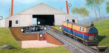

 The inclined planes that hauled the canal boats and barges up the mountain were engineering marvels in their day. The drawing (upper left) shows the concept for the 35hp steam plant, and a modern reconstruction (upper right) can be visited to see how they did it! Opportunities for modeling abound!
[Ed note: Thanks to Steve Russell, who called my attention to Funimag to show me the wonderful funicular that hauled Swiss chocolate to the top of a hill at the Suchard Chocolate Works (above right). The same issue has an article about the Allegheny Portage Railroad, which I visited in 2005 and photographed.]
REAL-LIFE INGLENOOK POSES PROTOTYPE PUZZLES
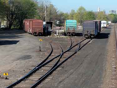
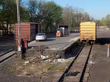
Stuart Pate, from Bolton, Connecticut USA, took these shots of a prototype Inglenook sidings that is in daily use in East Hartford, Connecticut on the Connecticut Southern Railroad. “It is used as a baled pulp transloading point for a small tissue mill that is located away from the tracks,” Stuart points out. “As you can see from the photos, it has the required three tracks, two of which are at a loading dock that holds two cars per side, while the third is used as a ‘hold’ track before and during switching.
“Normally, loaded cars are either brought in on the arriving train or stored on the right hand track. Upon arrival, the conductor of the train talks with the forklift operator on the dock to determine which cars have been emptied, and to receive instructions regarding the placement of the loads. Sometimes an outbound empty may be ‘buried’ behind a load, or a car may have a defective door on one side and have to be swung to the other side of the dock for access. Some of the inbound cars may have priority over others for unloading.
“For the modeler, this represents a simple prototype for a very small and operationally flexible layout. Scenicly it’s nothing more than the three ballasted tracks and a wedge shaped dock with a telephone pole and small red equipment box. It wouldn’t have to handle only boxcars like the prototype. Flatcars and gondolas loaded with steel, lumber, curbing stones, or farming equipment could conceivably arrive here. The forklift could be replaced by a mobile crane as needed.”
When I asked Stuart why he had such an intimate knowledge of this little scene, he confessed, “Yes, I’m an engineer on the CSOR in East Hartford, and I get to switch the ‘prototype inglenook’ almost daily. It’s a small part of the East Hartford yard. In one of the photos, you can see some track to the right, so if you had a spare couple of inches it would also be possible to have a length of track against the backdrop displaying some favorite cars.”
SMALL-FOOTPRINT PLAN PACKS IN PROTOTYPE TRACKAGE!
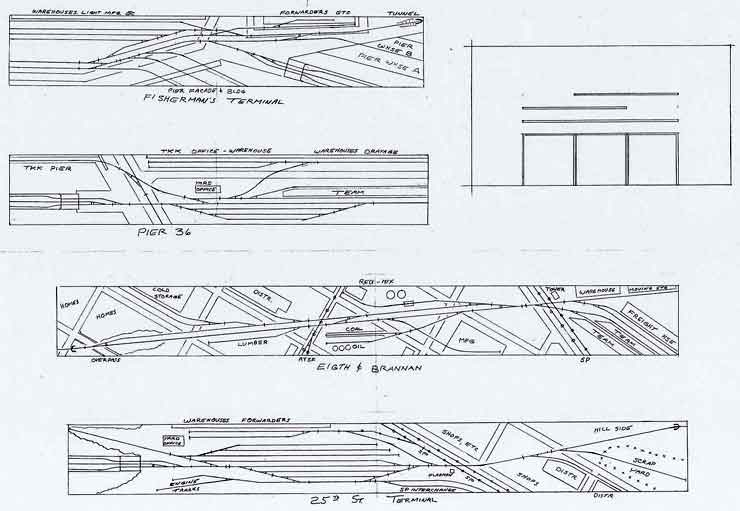
Mike McLaughlin, from Denver, Colorado USA, is a master at designing layouts that cram a huge knot of prototypical trackage into inconceivably small spaces. He writes, “Every year the Layout Design and Operations SIGs hold a joint meet in Santa Clara, California. One of the activities is a layout design challenge, and this year the subject was the China Basin area of San Francisco. The layout had to fit on top of a maximum of three 12x36in (30x90cm) book cases. Thought you might be interested in seeing what I came up with.”
Mike’s entry is illustrated above. It represents most of the interesting features of the Western Pacific’s West End line in San Francisco, which supported a highly profitable trade with the Orient. This N-scale railroad illustrates the line from its 25th Street Yard to the uptown industrial area, including the Asian terminal at Pier 36, and a speculative portrayal of WP involvement in barge traffic at Fisherman’s Terminal, Pier 43. The time frame is the mid-fifties with all-diesel motive power (except for the tugs plying the bay with the car barges in tow), mostly 40-foot cars, and heavy freight traffic to and from industries ranging from car-a-month to several cars per day.
Even in N scale this is an impossible amount of territory to cram into a 1x9ft space! So Mike’s design solution is to expand vertically. “Thus, the model Western Pacific RR West End is constructed on not only the three bookcases allowed, but also on three shelves tiered directly above them. The bookcases also represent Oakland staging and the connection with the outside world via several car barges that are stored there between runs.”
Space prevents us from presenting a detailed discussion of the WP West End operations, but briefly the scenario works like this. The 25th Street Yard, at bookcase level, receives cars from barges and assembles them into switch cuts in the yard, as well as shunting various industrial tracks in the area, all based on prototype trackage. The switch cut then starts up Portrero Hill at the right, diving into the Portrero Tunnel and onto a concealed three-foot (90cm) cassette track. It’s conveyed to the first shelf, reappearing at the other end of the prototype tunnel, ready to switch the prime industrial area between Portrero and Eighth & Brannon. Though selectively compressed, most of the major industries in the area are represented.
Another cassette trip gets the train to the third level, the waterfront with traffic to and from several piers coordinated in a small yard at Pier 36. The train continues to the fourth level, Fisherman’s Terminal with the Pier 43 barge slip. The modeled line ends in yet another tunnel, this time the line out to Fort Mason and the Presidio. Are you still with us?
The whole thing is intended as an out-front showpiece layout, with finished wood shelving and highly presentational scenery. Cars to be spotted would be placed on car barges destined for either 25th Street, Pier 36, or Fisherman’s Terminal, and placed on the bookcase shelves. The barges would be “towed across the bay” according to the marine schedule, and placed in the appropriate barge slips. The two smaller destinations would utilize single crews, but the 25th Street yard could have a boat job, a yard crew, and a switch-run crew. Operations can be as simple or as complex as desired.
And all of this takes place in a footprint of nine square feet!
[/vc_column_text][/vc_column][/vc_row]
Leave a Reply