PAGE 98 – June 2010
H O T I D E A S F O R S M A L L R A I L R O A D S
 Okay. Some folks like intensive switching activities (the Shelf People). Others prefer to run trains (the Circuit People). Can you do both on a small, standard gauge layout? Here are some ideas, including new plans from seven of the best small-layout designers.
In This Issue
Include an oval as part of your yard—some very compact combos
Add a temporary oval—a growing idea on the circuit
Designing the Switching Shelf—a Master Class
Chris Gilbert, Emrys Hopkins, Alexander Kaczmarek, Prof Klyzlr,
Jonathan Scott, ‘Shortliner’ Jack Trollope, Carl Arendt
Starter layouts to get you going
Eric’s Layout—a portable, 3-section HO layout
Taylor Creek Tramway—a first-time exhibition layout
ALTERNATIVE 1: INCLUDE AN OVAL AS PART OF YOUR YARD
This page is about having your cake and eating it too. It’s about making a layout with good operating possibilities—lots of switching cars and making up trains—but still allowing for some “train-running” action, going ’round in circles. All in the space of a Small Layout (under 24 square feet or 2.16 square meters).
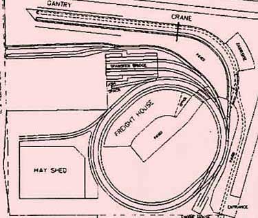
One good way to join switching with circular running is to make the circle an integral part of your train yard or switching district. The plan that comes to mind is those delightful little train-ferry yards that lined the rivers in New York City USA… like the Lehigh Valley’s Bronx Terminal on the Harlem River (upper left, click on diagram to reach an excellent page about this yard). Because land was scarce (and expensive), the prototype railroads had to curl their switching leads (head shunts) into a small, continuous oval shape to get the longest amount of track in the least space. They even built circular freight houses to use the space in the center!
We can work that same trick to get lots of operation and train-running in about 45x38in in HO scale (above right). Circlinglenook is designed entirely with Peco SeTrack, using its curved turnouts (three lefts) and taking advantage of its 17in (438mm) and 14in (371mm) curves. You can do a lot of shunting in this very small layout—even playing Inglenook games—and can still watch your locos log some miles. Adding a foot or so to the three yard tracks (by building a short extension) can add considerable capacity to this little yard. The stub at lower left can hold an engine house for the switcher.
Fishy Oval-Yard (left) illustrates a similar approach that offers good results for On30 trains in a similar space. It takes advantage of Fleischmann’s 10-inch-radius H0 curves to squeeze in an oval and uses a single Peco three-way turnout to create a “switching district.” The head shunt (yard lead) is also the main-line oval. Scenery can take many forms; the suggested theme of a fishing industry plays on the fact that there is a lot of Maine two-foot gauge equipment available for On30, and several of those little lines served waterfront areas.
ALTERNATIVE 2: ADD A TEMPORARY, REMOVABLE OVAL
If we can find or negotiate a little more space—at least on a temporary basis—then other alternatives appear, still within our “small layout” compass. One approach, currently gaining popularity, is to construct a small “shelf switcher” for everyday use… and when space is available (on the floor, on folding tables, or at a train show) connect the rest of an oval of track to the shelf. That way, we can have switching enjoyment all the time, and when we feel the urge, we can also run trains round and round! The oval can be made from pre-mounted trackage sections or just assembled from sectional track (preferably the kind with molded-in ballest).
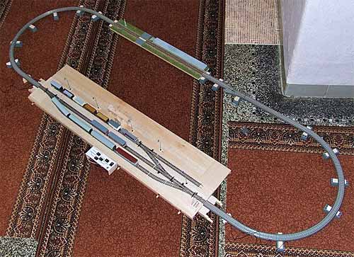
The Shelf-Plus-Oval idea is well illustrated by this layout sent in by Jiří Brožek, from Prague, the Czech Republic. Jiří built a TT-scale (1:20 on 12mm gauge) module of a small, local-line station. Then he connected the ends of the module with an oval of Tillig sectional track. “the layout had to be put together either on a large table or on the floor,” he commented. “TT is quite small, but not THAT small!”
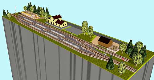
The photo at right shows the station module before scenery was installed. The drawing below shows the planned scenery. There’s a web page with more about this layout (in Czech, which Google Translations will handle for you). Jiří sent us this information in response to my questions about micro modules in Scrapbook #97a.
Jiří’s evaluation of the layout was not very favorable. “Unfortunately this idea had more cons than pros in the end… Especially the fact that the layout had to be put together on a large table or on the floor… [Also] As the station was built using Tillig profile track, I had to create two additional transitional segments that allowed me to use the sectional tracks for the track outside the station… As you may notice the module was higher (due to switching mechanisms) than the sectional tracks and they had to be bottomed on plastic bricks—another potential cause of problems. In the end I’ve abandoned the whole idea.”
But perhaps the idea has merit for others. We’ve noticed at train exhibitions (especially in continental Europe) an increasing number of layouts using this configuration—a beautifully detailed module, connected by a temporary oval of sectional track for running trains through. A good H0-scale example from Luxembourg is Timpas, a layout by Alain Kap shown in Scrapbook #89a.
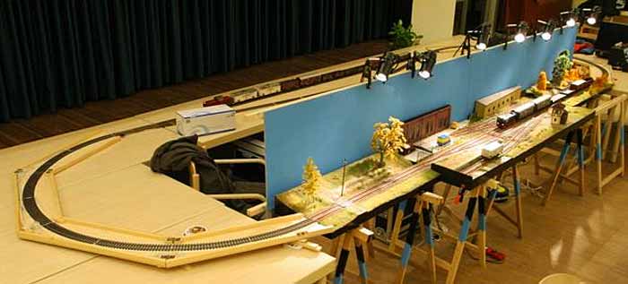
Another example (below) is an O-scale Timesaver built by Stefan Karzauninkat, from Hamburg, Germany. His home shelf-switcher layout is shown at an exhibition with a temporary oval laid out on a variety of tables (O scale is large!). For use at home, Stefan has included a meter-long module at each end of the Timesaver, to allow trains to pass all the way through the switching area. At exhibitions, he uses the pre-fab oval shown to keep the traffic flowing. There’s lots more information at his website, and in Scrapbook #83.
DESIGNING THE SWITCHING SHELF — A MASTER CLASS
I decided to explore further the idea of a shelf-switcher-with-removable-oval (SSRO) by trying a unique experiment. I invited six outstanding designers of small layouts to create a shelf plan intended to be used both by itself and with a removable oval. Works by each of these gentlemen have appeared many times in these pages, and I was confident they could test the limits of the idea with expertise and enthusiasm. The results have exceeded my highest expectations!
They are a globe-spanning group from England, Scotland, Germany, Australia and New Zealand. As you would expect, I added myself to the group to represent North America. I sent everyone a copy of the Czech layout photo above, and a request: “I’d appreciate it if you could sketch an idea for a 1×6 layout in HO scale (16.5mm gauge)—a permanent, landscaped switching layout that can operate by itself (or with a temporary cassette extension or two), but whose ends can be connected by a sectional-track oval when it’s time to run trains.”
The results are presented here in alphabetical order. —Carl Arendt
Chris Gilbert
West Midlands, England
Chris Gilbert is best known for layouts that ingeniously knot together a skein of gracefully curving trackage. Recently he’s been modeling U.S. prototypes, as in his current exhibition layout, Haston Nomad, set in Wisconsin. He also suggests a U.S. outline layout here, although the track plan would work well in almost any part of the world. Chris describes the layout like this: “Based on my Haston layout, I’ve added a run-around track and set it in New England as a small talc mill served by a U.S. Northeastern short line, NECR or the Vermont Railway (funny, I have those road engines sitting in front of me).
“When in shelf mode, the freight cars are pulled from the hidden siding [right rear], the loco runs round and switches the mill. All cars have to go via the scale track to be weighed in and out (adds another move). Hopper and tank cars go to the rear track while boxcars are loaded at the front. Outbound cars are pushed back into the hidden siding. The [suggested] river might be better as a road to keep the baseboard lower, making joining to the loop easier.
“Hm. I think I might try this one.”
Emrys Hopkins
Norfolk, England
Emrys Hopkins was one of the most prolific contributors to this site in its early days (2001-2). He quickly reached double digits in contributions to the Micro Layout Design Gallery (find his work in the Gallery Linked Index) and for a time was the most published author on the site (other than Carl). He has quieted down in recent years to pursue other projects, but came out of retirement for this occasion. His contribution embodies one of his “trademarks”—the use of both a three-way and a double-slip switch in a single design. Emrys has chosen to portray a gritty industrial switching yard and district that could be located anywhere worldwide. There are lots of places to spot cars, including a crane dock at the right, and there’s even a small (3-2-2 perhaps?) Inglenook in the left rear corner that can be switched without blocking the main line, so through trains can continue to pass.
Alexander Kaczmarek
Berlin, Germany
Alexander Kaczmarek is a photographer and artist as well as a layout designer, and his pictures, drawings, and track plans have appeared in these pages for the last several years. Alexander submitted two plans for this challenge, and invited us to take our pick. Naturally, we chose both!
The first, Mainlände Hafen, is a complicated design that flings spurs in all directions. Alexander comments, “At Mainlände you can find an extra runaround possibility and also a small harbour, but switching while the mainline is occupied is not possible in this configuration.” Nonetheless, the switching possibilities are tremendous, even if they do have to cease while the express train roars by. Both this and its sister layout (below) are designed to use Peco Code 75 track and turnouts, and both can be switched without the oval in place.
 Alexander’s second layout is named Krumme Fohre (a small station in northern Bavaria), and is also labeled Awanst. Alexander explained, “Awanst is the bureaucratic abbreviation for ‘Ausweichanschlussstelle’ (you notice the German preference for compound words).” It literally means “alternate interface.”
The three sidings in the yard are conveniently laid out as an Inglenook switching game, which provides one excellent mode for operation. As indicated on the diagram, there are lots of other good switching possibilities as well. Alexander concludes, “Awanst has the advantage that you can switch with one train in the sidings and at the same time a train can pass on the mainline. That´s exactly what we want, isn´t it?”
Prof Klyzlr
Sydney, Australia
“Prof Klyzlr” is the pseudonym of a well-known Australian model railroader whose work is often found on this site. His latest exhibition layout, Brooklyn: 3 AM, has been termed “a minimum-space masterpiece” and is one of only two layouts to have received an entire page of coverage here (the other is Chuck Yungkurth’s Gum Stump & Snowshoe). Prof, too, has been working on U.S. prototype layouts lately (his most recent is Chicago Fork), and he sent along two more for this challenge.
Prof declares, “The first plan, SP Secondary Main Line, takes advantage of a track arrangement that the Southern Pacific Railroad used in and around California, as documented and described by Bob Smaus in MR years ago. In short, SP effectively had a single-track mainline, and what ammounts to a long continuous ‘passing loop’ track which shadowed the mainline… a ‘secondary main.’ Fast freights and passenger trains stayed on the main line, while peddler freights switched industries off the secondary main.”
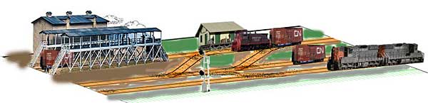
In this model layout the track at the front is the main line. It’s connected by a “high-speed crossover” to the secondary main (second track back) built at a lower level and with less-expensive ballast. The trackage behind the secondary main is inspired by the town of Arroyo on Smaus’s Espee layout “and presents a switching array which could be easy or hard depending on how the various tracks are cast. It’s begging to be switched with an SP tiger-stripe SW1 in an early era, or a Tiger-stripe SW1200 or speed-lettered SW1500 in a more modern vein. I would tend to cast the spur at rear left as a long industrial spur (oranges/fruit plant, with PFE reefers?) and the rear spur heading thru the mousehole [to an extension] at right as another big industry.” The scenery throughout is classic “SP in the desert.”
The Prof’s second layout is based on the scenic and operational appeal of a diamond junction between two railroads. Prof explains, “The arrow-straight track across the front is the Major RR Mainline and is the connection for the oval loop. The track through the diamond at right is a dummy but gives the opportunity for some token mainline junction signals, and maybe a tower. There are plenty of scenic details which can emphasise the fact that two seperate railroads are represented—different ballast colors and profiles, lineside structures, MOW details and more.
“The second track back is the interchange track. Under ‘loop mode’ a mainline freight can use either crossover to drop cars on the Interchange track. Under ‘shelf switcher” mode’ a mainline interchange turn can be staged on the Mainline to the west of the diamond and use the crossover next to the diamond to shove its cars into the Interchange track. To emphasise the main line nature of the front track, the crossovers are Peco Medium turnouts. The look of a pair of road diesels spotting interchange cars just begs to be modeled.
“The angled spur at top right is the interchange link track to the Other Railroad. With the addition of a ‘track on plank’ extension, it serves to stage a switcher and transfer caboose (caboose to the left, switcher to the right). In ‘shelf switcher’ mode, it’s the Other Railroad”s switcher that has the responsibility to switch and shuffle the interchange cars between both roads, using the interchange track and two-track drill yard at left.”
Prof suggested two possible prototype locations for this layout. Shown in the illustration is the interchange at Chattahoochee, Florida, between the CSX and the Apalachicola Northern. “This gives the modeler somewhere to run their fave Athearn AN SW1500s and some bigger CSX mainline power.” The other possibility is the open-prairie look of Hutchinson, Kansas, where the BNSF meets the UP. “This location is inspired by some YouTube clips of BNSF GP15u 3838 and mated ‘slug’ unit working the industries on the La Junta Sub.” As a special inducement, Prof points to a short clip taken at the diamond, which shows what happens if you don’t look where you’re going!
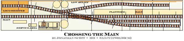
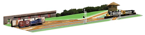
Jonathan Scott
Hamilton, New Zealand
Jonathan Scott teaches electronic engineering at the college level in Hamilton, New Zealand. His innovative micro layouts appear often in these Scrapbook pages. He’s currently on sabbatical leave, and we caught up with him in Anaheim, California USA, where he was attending a technical conference. He took some time out from the sessions to design a layout, for which we are very grateful. “What this layout offers,” Jonathan explained, “is the possibility of being both a run-through and a switching layout at the same time (or in isolation, just a shelf-switcher).
“The central straight through the double-slip is the mainline. While a train circulates on the mainline oval, a second loco can operate as a shunter assembling a train, ignoring the mainline but crossing it to access the farthest two sidings of a three-arm Inglenook yard. There is a natural frisson (chill of fear) associated with the need to cross the double-slip between passings of the circulating mainline train. Operations such as these are readily achieved with a DCC control system and perhaps an automatic system to flip the double slip into mainline position in response to approaching mainline traffic (entry of a vehicle onto the 6×1 baseboard).
“As ‘switcher-in-isolation’ the entry is at left middle, and the curved siding at top services several industries from which full cars are assembled into a mixed train along with a passenger carriage that rests adjacent to the platform.
“As ‘mainline-plus-yard’ there are now only two sidings apart from the top curved one, but pulling a car across has to await a suitable gap in traffic. Once assembled, the skillful operator may pull the assembled train out onto mainline in one of the gaps, follow the mainline train around a couple of times, then return to the siding, all without altering the speed of the mainline train or colliding with it. I know this to make a good test of a driver, as I use a similar sequence as the ultimate examination when I have a group of students demonstrating DCC controllers that they have built as part of a course I run at the university.”
Jonathan also contributed a unique idea for “scenery” around the sectional-track oval. “I am thinking that the run-around loop (oval) would be ad-hoc decorated with a selection of buildings and scenery objects as I use with a small live-steam 00 scale layout shown in this YouTube video.”
‘Shortliner’
Jack Trollope
Ross-shire, Scotland
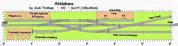
Jack Trollope currently holds the record for “most layouts published on this website by a single individual other than Carl.” Jack is a long-time member of municipal government who recently retired and continued to live in the Highlands at the far north of Scotland. Jack’s presence is widely felt on the Internet, and he also handles Internet communications and track plan preparation for the world’s best small-layout magazine, Model Trains International. About his layout, Attleboro, Jack wrote:
“I’ve gone back and re-worked a plan I first did 10 years ago—it’s still one of my favorites. It can be used in several ways.
“1. It can be a stand-alone shelf-switcher operated as-is, or extended with a Loco Lift at either end, or with departing cars on the interchange becoming inbounds for the next session.
“2. It can be operated as one main manufacturing plant for something like paper or potato chips, with added buildings, pipework, walkways between buildings, more tanks (washing/freezing/drying), parking for personnel cars, and truck delivery and loading bays.
“3. You can add a loop (oval) via each end and run a peddler freight that stops and drops its cars, pulls the departing stock from the interchange, puts arriving stock in to replace it, and then goes and circles the main for awhile until the local switcher comes and sorts the cars for the next session. If the peddler also does its own switching, the interchange track can be another set of spots.
“4. Hide a track inside a building (perhaps Foxy Lady) or behind one, with a cut-down Loco Lift for rotating, and break out the Trackmobile. Main line loco does the drop and pickups; Trackmobile does the running about.
“Note: Acme has two doors which require spotting as directed by the warehouse manager. Purely for scenic interest I’d find a diner with a couple of parked cars filling one of the spaces in the middle.”
Carl Arendt
Olympia, Washington, US
As the host of this party, I opted to appear last in line. For my contribution to this unique collection, I returned to a favorite theme—the RIP Track, where cars (and sometimes locomotives) come to be repaired. Specifically, I revisited my Carnegie Car Shops layout design. This tiny layout seemed to cry out to be larger and busier. And after working in the size of a sheet of letter paper, I felt this 6x1ft space was positively gargantuan! Also, I’ve recently moved from Pittsburgh (a neighbor of Carnegie, Pennslvania) to distant Olympia, Washington… so a new name was in order. Pencil was applied to paper, and here’s the result.
Appropriately, the new name is Olympian Car Shops. The backdrop, if there were one, would feature the beautiful, white-capped Olympic Mountains. But look here! I still haven’t been able to fill up the whole space! There’s plenty of room for some verdant Northwestern scenery… perhaps a logging camp. And there’s still a pretty complete car shop, including a large apron in front where some repairs can be made (and some nice equipment scattered about).
When the oval of mainline track is attached, a mainline train can stop by and drop off some cars in need of repair onto the long interchange siding beside the main. (A westward extension to the Yard Lead would help.) The foreman will assign each car to a track in the shop. When it’s time, the crew will fire up the Trackmobile and bring the car over to the shop, either in front or inside, depending on the repair required (which can be determined in the model by casting dice or pulling cards from a deck). The transfer table is ready to help move cars from track to track, as well as to deliver finished jobs directly to the interchange track. And every so often, a car of wheelsets arrives and needs to be hauled over to the wheel track, a very popular repair destination as well. For more operating details, see Rip Traxx’s prototype Car Shop description.
Old hands on this site will notice that the lower three spurs of the shop make a very nice Inglenook game board. And it can be worked while trains continue to circulate on the Main. So there you have it… a car shop writ large, but not very. I’m destined, it appears, to create very small layouts!
HOW TO GET STARTED… SOME GOOD BEGINNING LAYOUTS
For the benefit of beginners and newcomers to the hobby, we need to ask at this point: “What if I don’t know whether I like switching or running or both? I know that I don’t want to mess around with curved turnouts or complicated switching patterns. Is there any way for me to have a simple layout with a spot of switching and a bit of running, to try things on for starters?”
The answer of course is: Yes! We’ll be devoting a page to this question in the future. But for now, here’s a simple answer… a layout that is relatively easy to build, doesn’t require much investment of time or money, and gives a feel for the joys both of switching and of running trains.
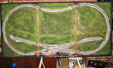
This little portable HO layout was built by Tom Schaeffer, from Boston, Massachusetts, USA, as a gift for his nephew, Eric, who lives in California, about 3,000 miles away. Overall the layout measures 70.5×34.5in (179x88cm). It is built—of necessity—in three sections which are stacked in a single carton for shipment from Massachusetts to California. Each section measures 23.5×34.5in and has a wooden frame filled with foam insulating board. Scenery and trains will be added at the other end of the trip.
Eric is seven years old and definitely qualifies as a beginner. The oval track for continuous running has an end radius of 16.5in (42cm), which limits rolling stock to small locomotives and 40ft cars. A lot of those models and kits are available, and they operate just fine on curves from 15in (38cm) on up.
As for switching, this layout follows the “Two Turnout Theme,” which offers excellent switching opportunities. Two previous Scrapbooks have been devoted to this switching theme—see #65a and #59a. As a general comment, the “kickback” siding will provide lots of opportunities for manipulating cars to get them to their designated spots on the layout. Put a five-car train together, designate three cars for spotting at selected places (chosen by lot, by dice, by pulling cards from a deck, etc.). Then go to it. You may find that you’ll need to “run around” a car in order to shove it into place. One good way to do that is to take the locomotive all the way around the oval. Works fine!
Above all, have fun. That’s what Eric’s Layout is for… and what model railways are really about!
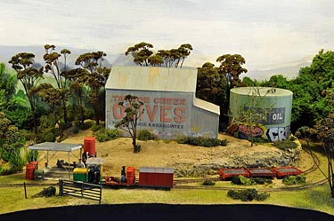
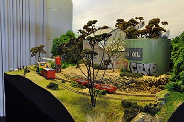
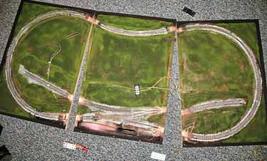
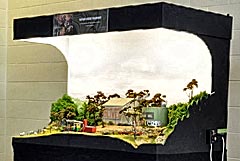 To demonstrate how a simple layout like Eric’s can be “dressed up” with excellent scenery, here’s Taylor Creek Tramway—an engaging little narrow-gauge layout. It’s the very first exhibition appearance by a younger modeler, Nathan Badcock, from Tasmania, Australia. Prof Klyzlr, in Sydney, sent these photos with the comment, “I have to say, it ticks all the right boxes for my mind re: Layout Presentation.” (See Scrapbook #95a for Prof’s opinions on this subject.) Photos are by Stuart Dix.
Note that the track plan for Taylor Creek Tramway is virtually the same as the one for Eric’s Layout. The addition of scenery makes a significant difference, doesn’t it? Notice particularly the changes in ground height (although the track is level); the use of varied ground cover, from dirt and gravel to tall grasses to rocky cuttings; the marvelous trees and other vegetation scattered about; and the convincing way the structures nestle into the landscape. Now imagine those elements applied to Eric’s Layout above… and get to work!
HELLO WOULD ANYONE HAVE A LAYOUT PLAN FOR THE HIGHLANDER TERMINALS IN N SCLAE I WOULD BE WILLING TO PAY FOR THEM THANKS STEVE OHIO